Imager and Imaging Method for Digital Cinematography

a digital cinematography and imager technology, applied in the field of television cameras, can solve the problem of limited image resolution of conventional solid-state imaging devices

Inactive Publication Date: 2009-11-12
THOMSON LICENSING SA
View PDF4 Cites 13 Cited by
  • Summary
  • Abstract
  • Description
  • Claims
  • Application Information

AI Technical Summary

Problems solved by technology

The resolution of images obtained with conventional solid state imaging devices is limited by the rate at which the camera can scan the imaging area.

Method used


Image

  • Imager and Imaging Method for Digital Cinematography
  • Imager and Imaging Method for Digital Cinematography
  • Imager and Imaging Method for Digital Cinematography

Examples


Embodiment Construction
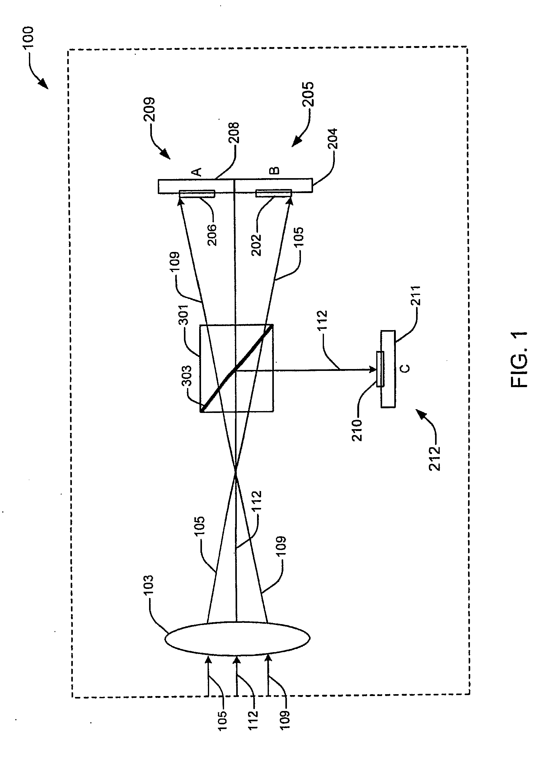
[0012]FIG. 1

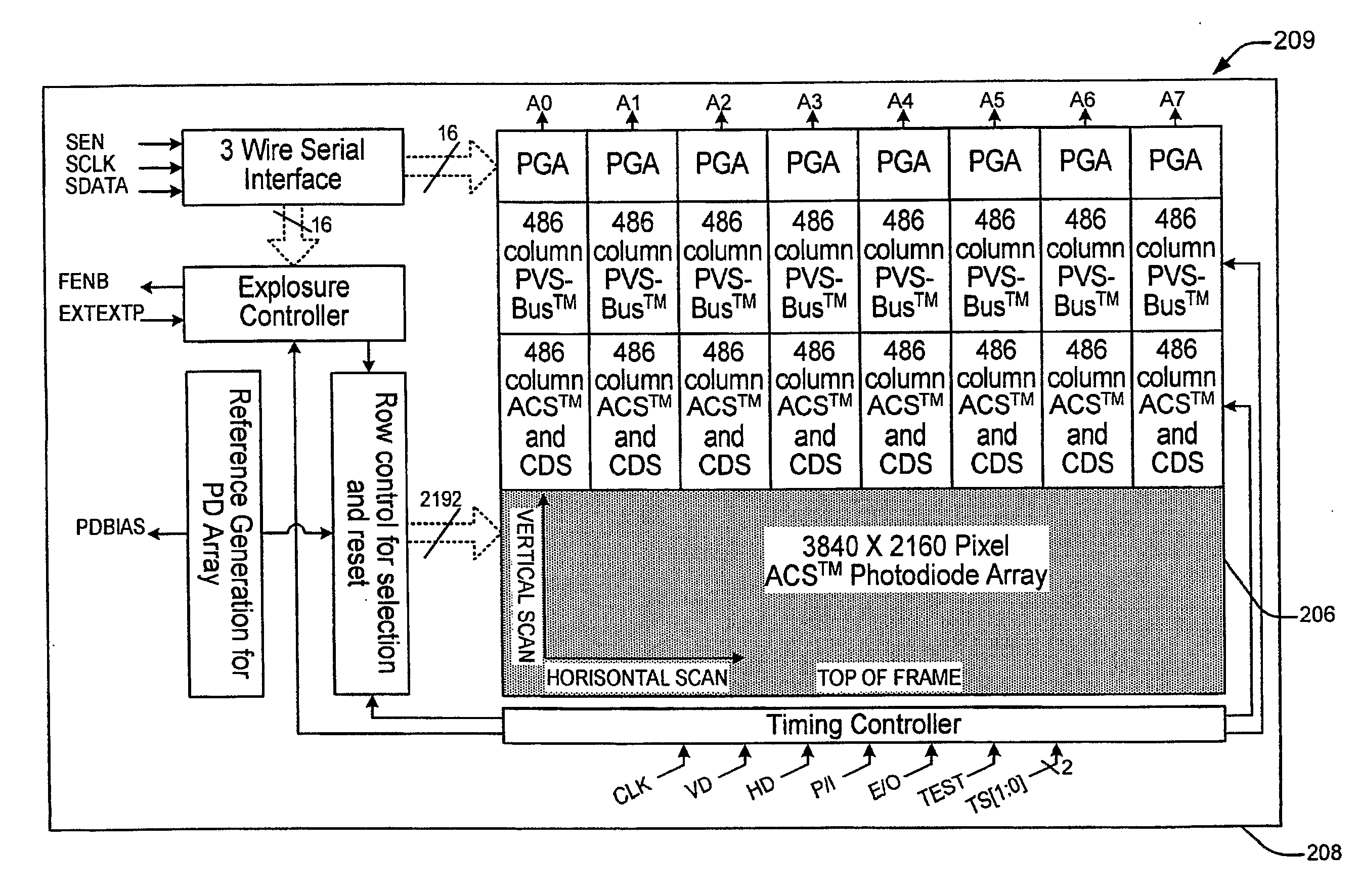
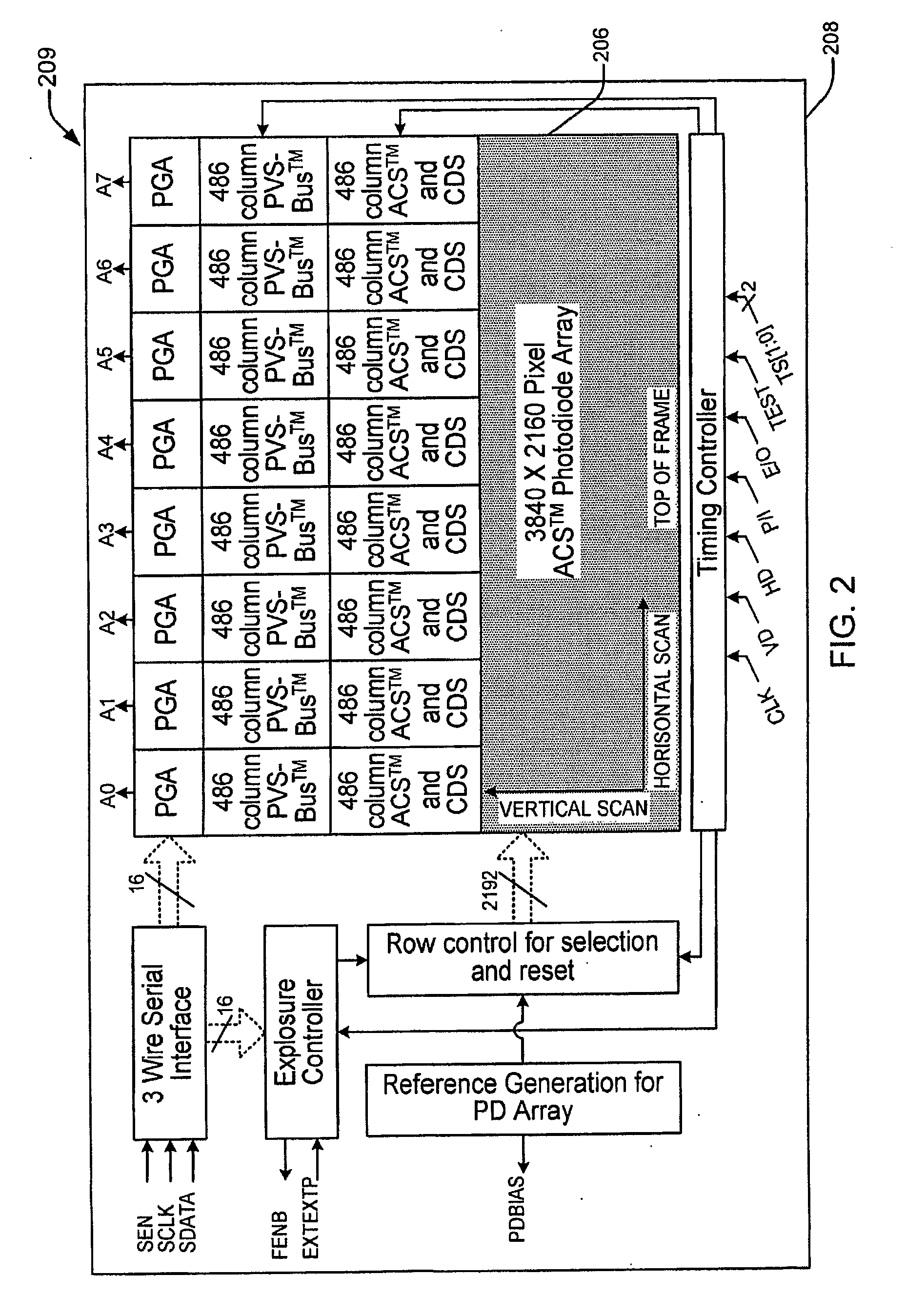
[0013]FIG. 1 illustrates an imager 100 according to an embodiment of the invention. Imager 100 comprises three video image sensor packages (209, 205 and 212). Each image sensor package comprises photo-sensing elements arranged in an array (206, 202, 210). Each array (206, 202, 210) is disposed on a respective substrate (208, 204, 211). Imager 100 further comprises a lens 103 and an optical beam splitter 301. Conventional circuits and components comprising imager 100 according to embodiments of the invention are not illustrated in FIG. 1 for ease of discussion of the invention.

[0014]Imager 100 forms an optical image of an object 9 (illustrated, for example in FIG. 3). For purposes of this specification the term “object” refers to an object or objects comprising a scene to be captured by the imager for subsequent display to a viewer on a display device. Lens 103 focuses light from object 9 (represented generally by lines 105, 112 and 109) onto photoelements of arrays 206, ...


PUM


Abstract

The invention provides an imager and imaging method for forming, on a plurality of photo-elements, an optical image of an object lying in a viewing plane defined by horizontal and vertical viewing axes. The imager comprises at least first, second and third video image sensors. Each video image sensor comprises a corresponding array of photoelements. The photoelements are arranged in rows and columns to define a first pixel resolution for each array. A lens is configured to focus at least a portion of light from the object onto the arrays. The arrays are arranged with respect to the lens such that the rows are aligned along avertical axis of the viewing plane. The columns are aligned along a horizontal axis of the viewing plane. An optical image of the object is formed. The image comprises a second pixel resolution higher than the first pixel resolution.

Description

CROSS-REFERENCE TO RELATED APPLICATIONS[0001]This invention claims priority to U.S. provisional application Ser. No. 60 / 751,336 filed in the United States Patent and Trademark Office on Dec. 16, 2005 for MATRIX DISPLAY SYSTEM AND METHOD, to inventor Mark Alan SchultzFIELD OF THE INVENTION[0002]The invention relates generally to television cameras and more particularly to high definition solid-state imagers for use in digital cinema television cameras.BACKGROUND OF THE INVENTION[0003]Television cameras produce an optical image of an object on an imaging area of a solid-state imaging device. The imaging area is typically defined by an array comprising rows and columns of photo-elements. The camera scans the charges on the photo-elements at a scanning frequency. The camera converts the charges to an electrical signal representing an image of the object. The scanning frequency corresponds to the television system employed. For example., in the NTSC system a scanning frequency of 60 fiel...

Claims


Application Information

Patent Timeline
Patent Type & Authority Applications(United States)
IPC IPC(8): H04N5/225
CPCH04N5/2253H04N9/3197H04N9/3147H04N23/54
Inventor SCHULTZ, MARK ALAN
Owner THOMSON LICENSING SA
Why Eureka
Try Eureka