Latch for Securing a Hardware Component Into a Component Bay

a hardware component and latch technology, applied in the direction of furniture parts, electrical apparatus casings/cabinets/drawers, instruments, etc., can solve the problems of hard disk drives being dislodged from the interfaced position or disconnected from the hos

Active Publication Date: 2009-11-12
LENOVO GLOBAL TECH INT LTD
View PDF27 Cites 39 Cited by
  • Summary
  • Abstract
  • Description
  • Claims
  • Application Information

AI Technical Summary

Benefits of technology

[0009]In a preferred embodiment, the hard disk drive is designed to assist in the installation of the carrier into a bay. Accordingly, pivotal movement of the handle from an open position to an intermediate position deploys the latch key beyond a lateral edge of the frame for engagement with a slot in a disk drive bay sidewall. Further pivotal movement of the handle from the intermediate position to closed position causes the extendable arm to retract to follow the contour of the disk drive bay sidewall and draws the latch key in a proximal direction.
[0010]In a further preferred embodiment, the hard disk drive is designed to assist in the removal of the carrier from a bay. Accordingly, pivotal movement of the handle from a closed position to an intermediate position causes the stop arm to engage the bay and the extendable arm to extend to follow the contour of the disk drive bay sidewall and moves the latch key in a distal direction. Further pivotal movement of the handle from the intermediate position to the open position biases the stop arm against the bay to disengage the hard disk drive from its coupling with a host computer and disengages the latch key from the slot in the disk drive bay sidewall.

Problems solved by technology

The motor that rotates the hard disk and the actuator that positions the head to read from the hard disk or write to the hard disk typically cause vibrations that can result in the hard disk drive becoming dislodged from the interfaced position or disconnected from the host system in the absence of the latch apparatus.

Method used


Image

  • Latch for Securing a Hardware Component Into a Component Bay
  • Latch for Securing a Hardware Component Into a Component Bay
  • Latch for Securing a Hardware Component Into a Component Bay

Examples


Embodiment Construction

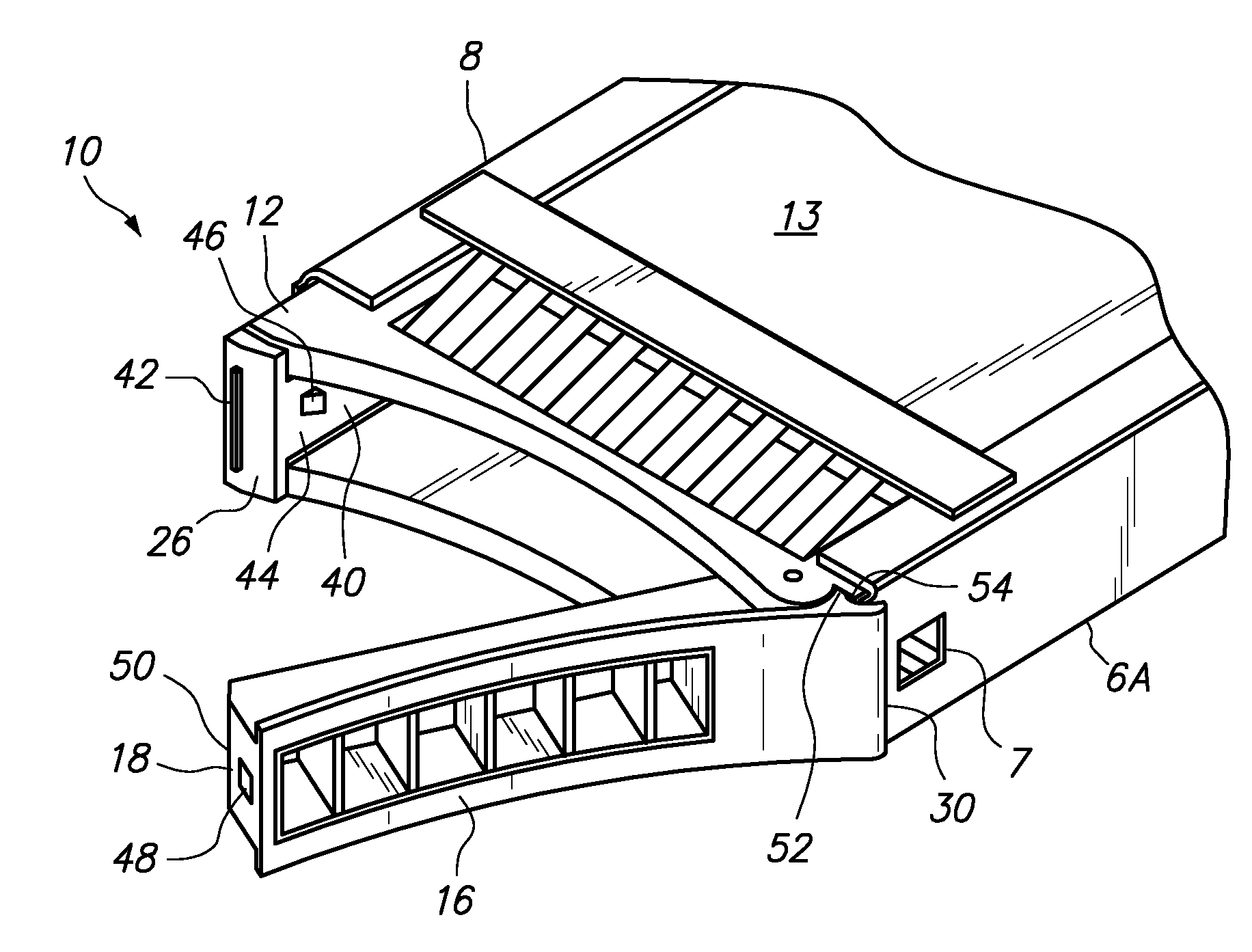
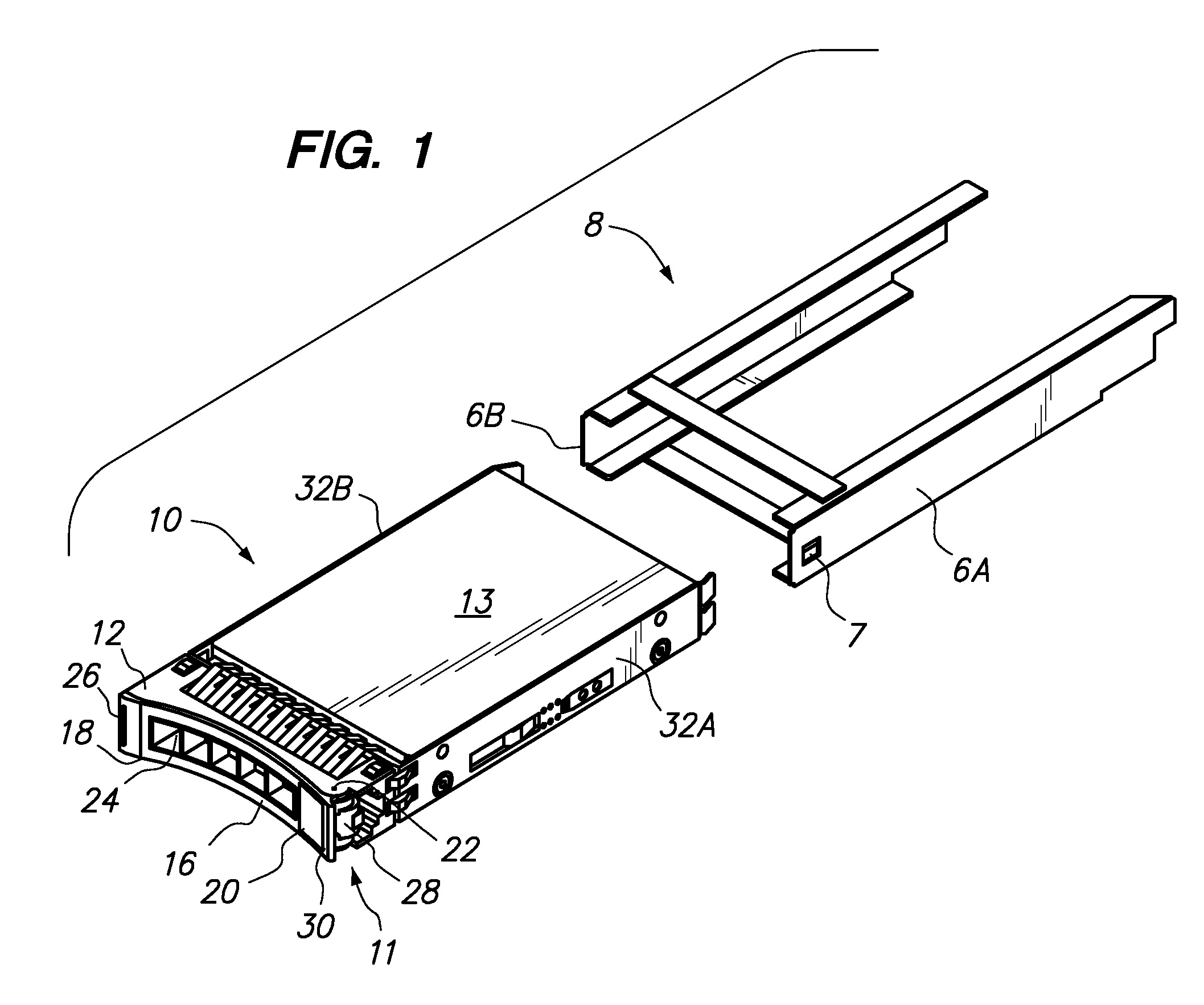
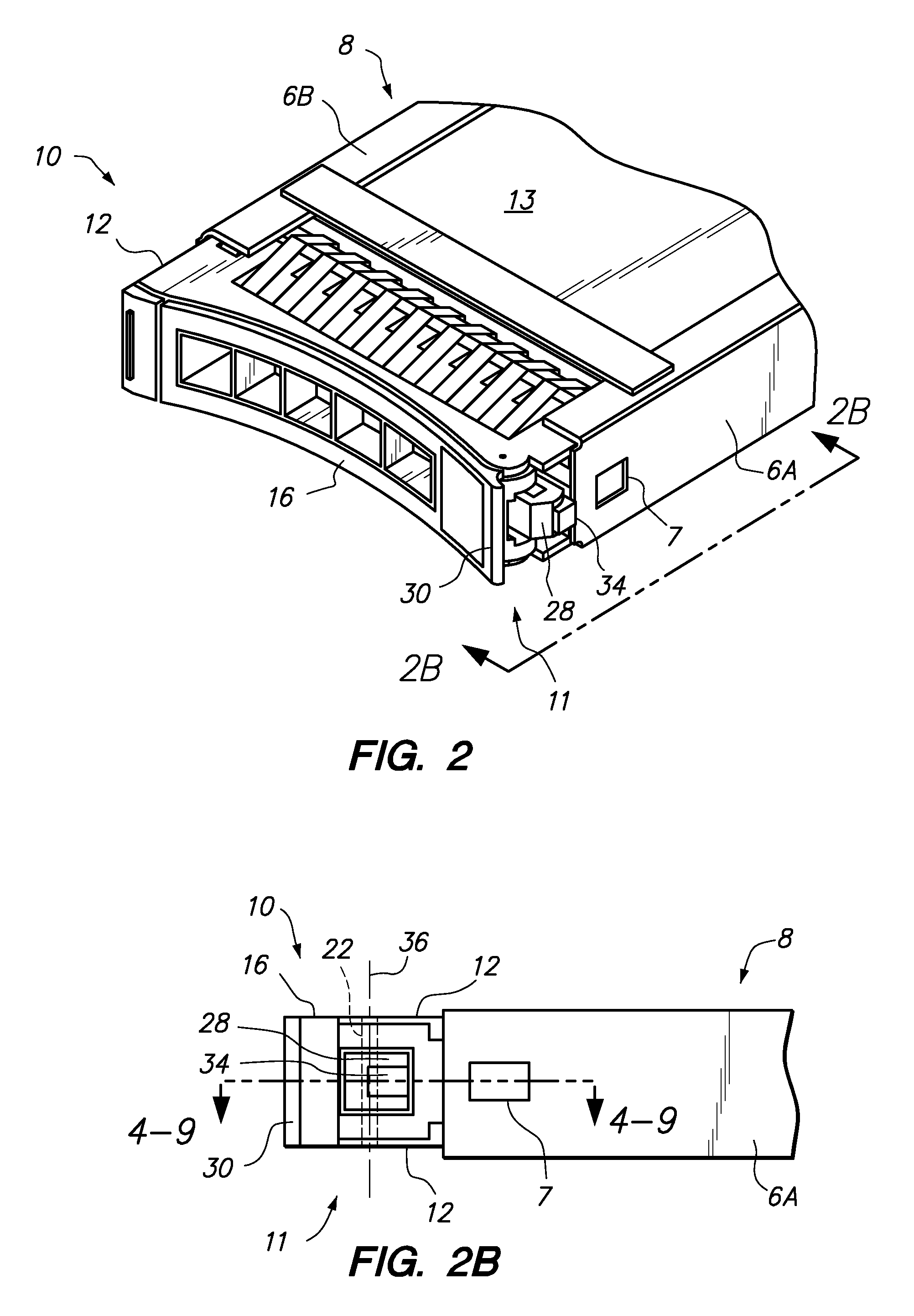
[0023]The present invention provides a latch for securing a hardware component, such as a disk drive, into a component bay forming part of a computer system. Although the invention is described herein in the context of a hard disk drive carrier, it should be recognized that the latch may be implemented to secure other hardware components into a component bay in a similar manner. The latch is particularly beneficial for securing a hardware component has an external connector that requires electronic coupling to a mating connector positioned within the component bay.

[0024]One embodiment of the present invention provides a hard disk drive carrier, comprising a frame adapted to be secured to a proximal end of a hard disk drive housing, a handle pivotally secured to the frame intermediate a proximal end and a distal end of the handle, and an extendable arm that is slidably secured to the distal end of the handle and biased toward an extended position. The extendable arm has a distally ex...


PUM


Abstract

A latch apparatus and method to facilitate leveraged insertion of a component into a component bay to an interfaced position, securing of the component in the component bay when the component interfaces with a host computer, leveraged dislodgement of the component from its interfaced position for removal of the component from the component bay, and proper positioning of the latch apparatus upon insertion of the component housing to ensure proper engagement of the latch apparatus with the component bay for leveraged insertion and removal. One latch apparatus comprises a frame adapted to be secured to a proximal end of a component housing, a handle pivotally secured to the frame, and an extendable arm slidably secured to a distal end of the handle and biased toward an extended position, wherein the distal end of the extendable arm has a distally extending latch key for engaging a slot in the component bay.

Description

BACKGROUND OF THE INVENTION[0001]1. Field of the Invention[0002]The present invention relates to a latch for securing a hardware component, such as a disk drive, into a component bay forming part of a computer system.[0003]2. Background of the Related Art[0004]Hard disk drives generally include a data storage disk secured within a housing that may be coupled to a carrier, sometimes referred to as a tray, which is adapted to be received and secured in a drive bay to interface with a host computer. For example, a generally circular data storage disk is rotatably coupled within the housing in a position to rotate relative to the housing and about a generally vertical axis. A disk reader head is also movably coupled within the housing to controllably track across the rotatable data storage disk to retrieve data stored on the disk, or to retrievably write data to the disk.[0005]A plurality of hard disk drives may be arranged within an array of bays within a chassis. This configuration en...

Claims


Application Information

Patent Timeline
Patent Type & Authority Applications(United States)
IPC IPC(8): H05K7/00G06F1/16
CPCG06F1/187G11B33/124G11B33/123
Inventor CRIPPEN, MARTIN JOSEPHKERRIGAN, BRIAN MICHAELPIPER, CHARLES WILLIAMTRUMBO, BRIAN ALAN
Owner LENOVO GLOBAL TECH INT LTD
Why Eureka
Try Eureka