
Waste processing apparatus and method featuring water removal

Active Publication Date: 2008-09-11
ESTECH
View PDF26 Cites 53 Cited by
  • Summary
  • Abstract
  • Description
  • Claims
  • Application Information

AI Technical Summary

Benefits of technology

[0018]The arrangement of the blades and the interior of the vessel preferably are such that there are essentially no surfaces against which the charge of waste products may become compressed laterally during rotation of the vessel; i.e., in a direction parallel to the longitudinal axis of the vessel; and that an open central region is provided through substantially the entire length of the vessel (i.e., the treatment space of the vessel). Such an arrangement permits portions of the charge of waste products to be transported from the bottom of the vessel toward the top of the vessel during rotation, and released to fall to the bottom of the vessel through the pressurized steam environment as discreet relatively low density portions to increase the surface area of that portion with respect to the steam environment of the vessel.
[0060]Accordingly, another aspect of the present invention is the provision of a high vessel pressure (typically above about 5 atmospheres) to assist in the dewatering and drying of the vessel contents. Experimentation has shown that a residual water concentration below about 20% is achievable. The present invention thus allows for the vessel to be re-pressurized with air or steam to assist in the pressure-forced removal of water.

Problems solved by technology

One of the disadvantages of the arrangements of the prior art is that portions of the waste product charge in the vessel become compacted, either passively by maintaining the vessel at a fixed position with respect to the horizontal, or actively through the use of spiral or helical rib arrangements that urge portions of the charge against active surfaces in a horizontal direction (or a direction parallel to the longitudinal axis of the vessel) as the vessel is rotated.
Another disadvantage of the prior art is that prior systems and methods do not allow for the most advantageous control and distribution of energy placed into the vessel, and its efficient transfer to the waste charge mass.
This made an economically and technically viable industrial process for the treatment of waste less than efficient.
However, this process requires a separate steam treatment during loading which results in greater overall time requirements for each waste batch.
As excess water typically must be removed by active drying, this requires additional time and energy investment.

Method used


Image

  • Waste processing apparatus and method featuring water removal
  • Waste processing apparatus and method featuring water removal
  • Waste processing apparatus and method featuring water removal

Examples


Embodiment Construction

[0075]In accordance with the foregoing summary, the following provides a detailed description of the preferred embodiment, which is presently considered to be the best mode thereof.

[0076]The invention relates to a process for recycling waste. This process is sterilizing high density materials such as glass, plastics, metals and recovering others from municipal solid waste (MSW) and converting paper, cardboard, food waste, etc. to a usable fiber and separating it from other recyclable materials.

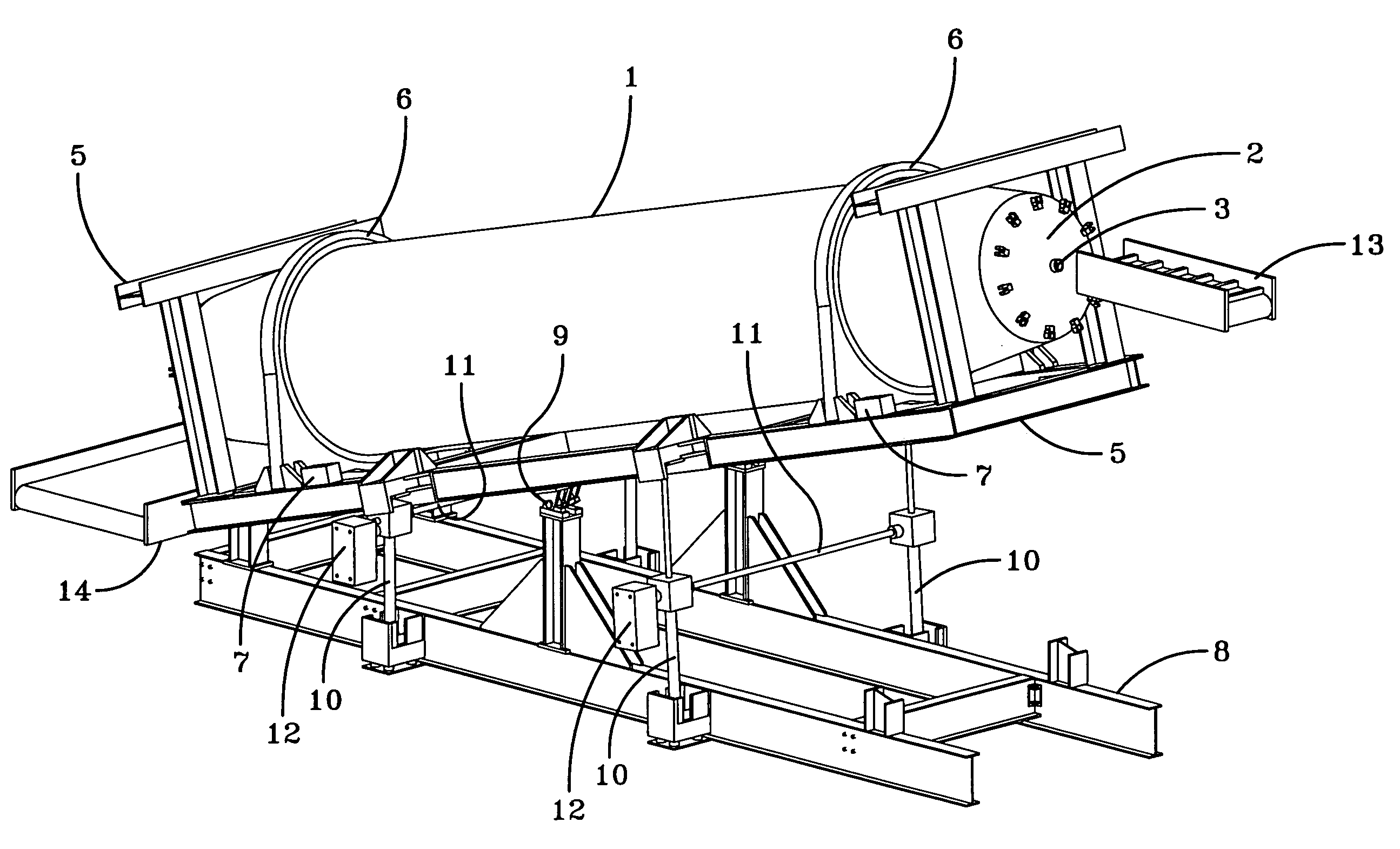
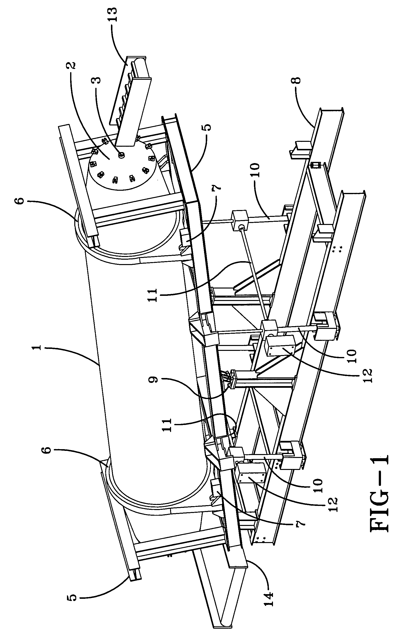
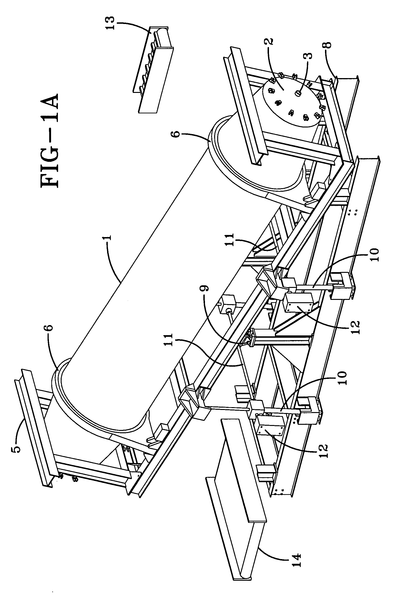
[0077]FIG. 1 shows an example of an apparatus for processing solid waste products in accordance with one embodiment of the present invention.

[0078]FIG. 1 shows a rotatably mounted cylindrical vessel 1 having a first end, a second end and an interior surface, at least one end terminating in a hatch 2 that may be opened to allow access to the interior of the vessel and sealed closed to allow pressurization of the vessel. It is preferred that the vessel have a hatch on either end such that the ve...


PUM


Abstract

The present invention includes an apparatus and method for processing solid waste products. The invention features periodic removal of water preferably while the contents are under pressure. The apparatus comprises a rotatably mounted cylindrical vessel having a first end, a second end and an interior surface, at least one end terminating in a hatch that may be opened to allow access to the interior of the vessel and sealably closed to allow pressurization of the vessel; a steam inlet for injecting stem disposed at one or both ends; and one or more valves for exhausting water periodically as the waste mass is being processed.

Description

TECHNICAL FIELD[0001]The present invention relates to the treatment of municipal solid waste and the like.BACKGROUND OF THE INVENTION[0002]The present invention relates to systems and methods for treating process material and, more particularly, to systems and methods for treating municipal solid waste material, medical waste material, reclaimed paper and the like.[0003]As a result of increasing scarcity of landfills and more stringent environmental regulations, efforts have been made to reduce the volume of process material, such as municipal solid waste (“MSW”) and paper material, such as newsprint and other reclaimed and recycled paper products as a step in the process of disposing of the material, either by depositing it in landfills, incinerating it or recycling it.[0004]Systems and methods have been developed to break down such material for disposal, or in the case of paper products, use as insulation.[0005]An example of such a process and device is U.S. Pat. No. 5,190,226, wh...

Claims


Application Information

Patent Timeline
IPC IPC(8): B02C19/00
CPCA61L11/00B01F9/06B09B3/00F26B11/049C10L9/086F26B11/028B09B3/0091B09B3/45B01F29/63
Inventor MICHALEK, JANTHOMAS, THEODORE
Owner ESTECH
Learn More