
Fluid dynamic bearing apparatus

a dynamic bearing and fluid technology, applied in mechanical equipment, sliding contact bearings, mechanical energy handling, etc., can solve the problems of insufficient tolerance for moment load, inability to meet the requirements of reducing the thickness of the bearing apparatus, and inability to lubricating oil in the sealing space may undetectedly leak to the outside of the bearing, etc., to achieve high sealing performance, reduce the axial dimension of the sealing portion, and reduce the sealing capacity in the sealing space

Inactive Publication Date: 2009-11-12
NTN CORP
View PDF5 Cites 12 Cited by
  • Summary
  • Abstract
  • Description
  • Claims
  • Application Information

AI Technical Summary

Benefits of technology

[0007]Furthermore, thrust bearing portions T are provided on both sides of the flange portion of the shaft member 20 so that the axial distance between both thrust bearing portions T, T is reduced. Therefore, the value of tolerance for the moment load by the thrust bearing portion T tends to be lowered correspondingly. In particular, in case of a hydrodynamic bearing apparatus for use in a disk drive unit, a relatively large moment load acts on the shaft member 20 as a rotor (body of rotation having a rotor hub, rotor magnet, disk, clamper and other components mounted thereon) rotates, and therefore moment load capacity is a significant characteristic.
[0027]According to the present invention, a fluid dynamic bearing apparatus having high sealing function, in addition to the high value of tolerance for the moment load, can be provided.

Problems solved by technology

This increases the separation distance between the bearing center of the radial bearing portion R and the center of gravity of the body of rotation, and a value of tolerance for moment load may be insufficient depending on the used conditions and the like.
Moreover, to ensure the buffering function of the sealing space S, the axial dimension of the sealing space S (sealing portion 100) has to be inevitably large, but this makes it difficult to meet the requirements of reduction in thickness of bearing apparatuses.
Moreover, in order to enhance the buffering function of the sealing space S, a method of reserving a large opposing interval between the inner circumferential surface of the sealing portion 100 forming the sealing space S and the outer circumferential surface of the shaft member 20 is also possible, but in this manner, the lubricating oil in the sealing space S may undesirably leak readily to the outside of the bearing upon impact or due to other causes.

Method used


Image

  • Fluid dynamic bearing apparatus
  • Fluid dynamic bearing apparatus
  • Fluid dynamic bearing apparatus

Examples


first embodiment

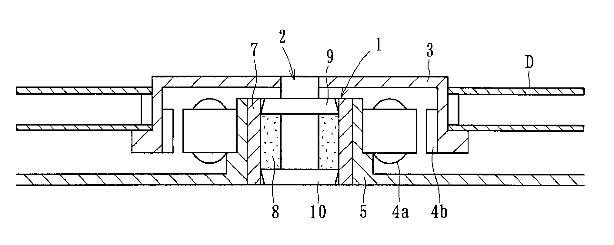
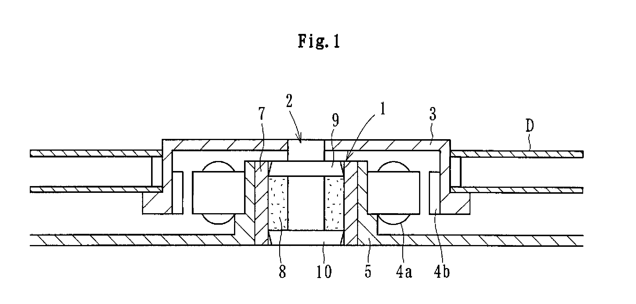
[0044]FIG. 1 conceptionally shows a constitutional example of a spindle motor for information appliances integrating the fluid dynamic bearing apparatus (hydrodynamic bearing apparatus) 1 according to the present invention. This spindle motor for information appliances is for use in a disk drive unit such as HDD, and comprises a fluid dynamic bearing apparatus 1, a rotor (disk hub) 3 attached to a shaft member 2 of the fluid dynamic bearing apparatus 1, a stator coil 4a and a rotor magnet 4b which, for example, oppose each other across a gap in the radial direction, and a bracket 5. The stator coil 4a is attached to the outer periphery of the bracket 5, and the rotor magnet 4b is attached to the inner periphery of the disk hub 3. The disk hub 3 retains one or more disks D such as magnetic disks on its outer periphery. When the stator coil 4a is energized, the rotor magnet 4b is rotated by the electromagnetic force generated between the stator coil 4a and rotor magnet 4b, and the dis...

sixth embodiment

[0078]the present invention will be described below with reference to FIGS. 13 to 15.

[0079]FIG. 13 conceptionally shows a constitutional example of a spindle motor for information appliances integrating a fluid dynamic bearing apparatus (hydrodynamic bearing apparatus) 21 according to the sixth embodiment of the present invention. This spindle motor is for use in a disk drive unit such as HDD, and comprises a fluid dynamic bearing apparatus 21 which rotatably supports a shaft member 22, a disk hub 23 fixed on the shaft member 22, a stator coil 24 and a rotor magnet 25 which, for example, oppose each other across a gap in the radial direction, and a bracket 26. The stator coil 24 is attached to the outer periphery of the bracket 26, and the rotor magnet 25 is attached to the inner periphery of the disk hub 23. The fluid dynamic bearing apparatus 21 is fixed to the inner periphery of the bracket 26. One or more (two in FIG. 13) disks D as information recording media are retained on th...


PUM

PropertyMeasurementUnit
Diameteraaaaaaaaaa
Hydrodynamic waveaaaaaaaaaa

Abstract

A fluid dynamic bearing apparatus having an increased a value of tolerance for a moment load is provided.A cylindrical sleeve portion 8 is fixed to the inner periphery of the housing 7 whose both ends are open, and a shaft member 2 is further inserted at the inner periphery of the sleeve portion 8. Sealing portions 9, 10 are fixed to the shaft member 2 in the manner of nipping the sleeve portion 8 from both sides in the axial direction, and sealing spaces S1, S2 having the oil level of a lubricating oil are formed between the outer circumferential surfaces 9a, 10a of the sealing portions 9, 10 and the inner circumferential surface 7a of the housing 7. The radial bearing gap between the inner circumferential surface 8a of the sleeve portion 8 and the outer circumferential surface 2a of the shaft member 2 is formed and thrust bearing gaps are formed between the end faces 9b, 10b of the sealing portions 9, 10 and the end faces 8b, 8c of the sleeve portion 8 opposing these to support the shaft member 2 in a non-contact manner in the radial direction and in the thrust direction by the hydrodynamic effect of the lubricating oil produced in each bearing gap.

Description

BACKGROUND OF THE INVENTION[0001]The present invention relates to a fluid dynamic bearing apparatus which relatively rotatably supports a shaft member by a lubricating film of a fluid produced in a bearing gap.[0002]Fluid dynamic bearing apparatuses are recently used as bearings for motors mounted on information appliances and various other electrical machinery and apparatuses because of their excellent rotational accuracies, high-speed rotation properties, quietness and other properties. More specifically, fluid dynamic bearing apparatuses are used as bearing apparatuses for spindle motors mounted on information appliances such as for HDD and like magnetic disk apparatuses, CD-ROM, CD-R / RW, DVD-ROM / RAM and like optical disk apparatuses, and MD, MO and like magneto-optic disk apparatuses, and as bearing apparatuses for polygon scanner motors for laser beam printers (LBP), collar wheel motors of projectors, and motors such as fan motors and the like.[0003]Fluid dynamic bearings of th...

Claims


Application Information

Patent Timeline
IPC IPC(8): F16C32/06
CPCF16C17/107Y10T29/49639H02K7/085F16C33/107F16C17/00F16C33/74H02K7/08
Inventor SHIMIZU, KAZUTOMIZUTANI, TOSHIYUKIHORI, MASAHARU
Owner NTN CORP
Learn More