Rolling roll, rolling ring, rolling mill, and rolling roll assembling method

a technology of rolling mills and rolling rolls, which is applied in the direction of manufacturing tools, mechanical equipment, and portable power-driven tools, etc., can solve the problems of general brittleness and inability to withstand tensile force, cracks in the outer circumferential surface, and inability to satisfactorily roll, so as to reduce the amount of hard materials, prevent cracks, and reliably prevent tensile stress

Inactive Publication Date: 2009-11-12
MITSUBISHI MATERIALS CORP
View PDF10 Cites 6 Cited by
  • Summary
  • Abstract
  • Description
  • Claims
  • Application Information

AI Technical Summary

Benefits of technology

[0009]To prevent a crack from occurring, the conventional approach is to ensure the rigidity of the rolling ring 8 by increasing its wall thickness in the radial directions and its length in the directions of the axis L; however, in such a case, the portion of the rolling ring 8 that is used for rolling becomes relatively small compared with the entire rolling ring 8, which increases the amount of the cemented carbide material used beyond what is necessary; thereby, the manufacturing cost of the rolling ring 8 increases substantially.
[0027]The present invention can provide: a rolling roll wherein it is possible to prevent cracks from occurring by preventing tensile stress from acting on the outer circumferential surface of a rolling ring, and to reduce operating costs significantly by reducing the size of the rolling ring, which is made of a hard material such as cemented carbide; a rolling ring that constitutes the rolling roll; a rolling mill that is provided with the rolling roll; and a method of assembling the rolling roll.

Problems solved by technology

Here, the hard material, e.g., cemented carbide, is generally brittle and unable to withstand tensile stress; consequently, cracks form in the outer circumferential surface of the rolling ring 8.
If a crack forms in the outer circumferential surface of the rolling ring 8, there is a risk that the metal material and the like will get into the crack and make it impossible to perform rolling satisfactorily, and also that the crack will enlarge and cause the rolling ring 8 itself to break.
Consequently, if a crack occurs, there is a problem in that the rolling ring 8 must be replaced as soon as possible, which significantly increases the operating cost of the rolling roll 1.
To prevent a crack from occurring, the conventional approach is to ensure the rigidity of the rolling ring 8 by increasing its wall thickness in the radial directions and its length in the directions of the axis L; however, in such a case, the portion of the rolling ring 8 that is used for rolling becomes relatively small compared with the entire rolling ring 8, which increases the amount of the cemented carbide material used beyond what is necessary; thereby, the manufacturing cost of the rolling ring 8 increases substantially.
Furthermore, in order to smoothly finish the surface of the rolled product (e.g., a wire or a bar), it is preferable to form the rolling ring 8 with a material that is as hard as possible; however, high-hardness materials tend to be even more brittle and unable to withstand tensile stress, which tends to produce cracks; consequently, the conventional art is unable to improve the surface state of the product by forming the rolling ring 8 with a material of high hardness.

Method used


Image

  • Rolling roll, rolling ring, rolling mill, and rolling roll assembling method
  • Rolling roll, rolling ring, rolling mill, and rolling roll assembling method
  • Rolling roll, rolling ring, rolling mill, and rolling roll assembling method

Examples


eighth embodiment

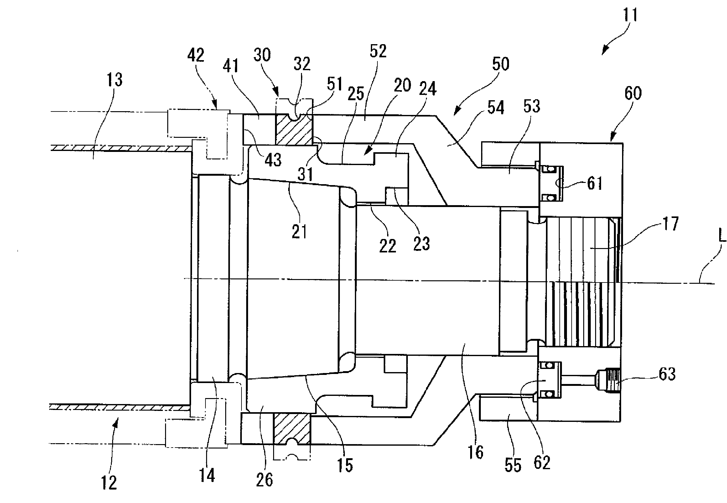
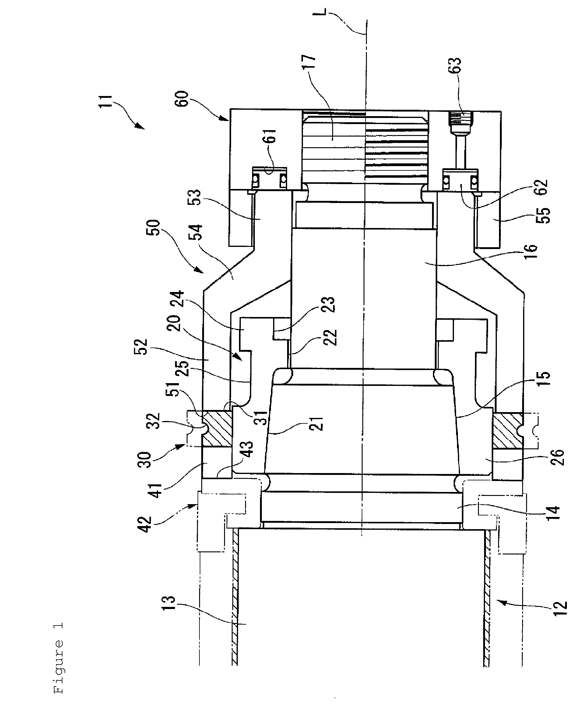
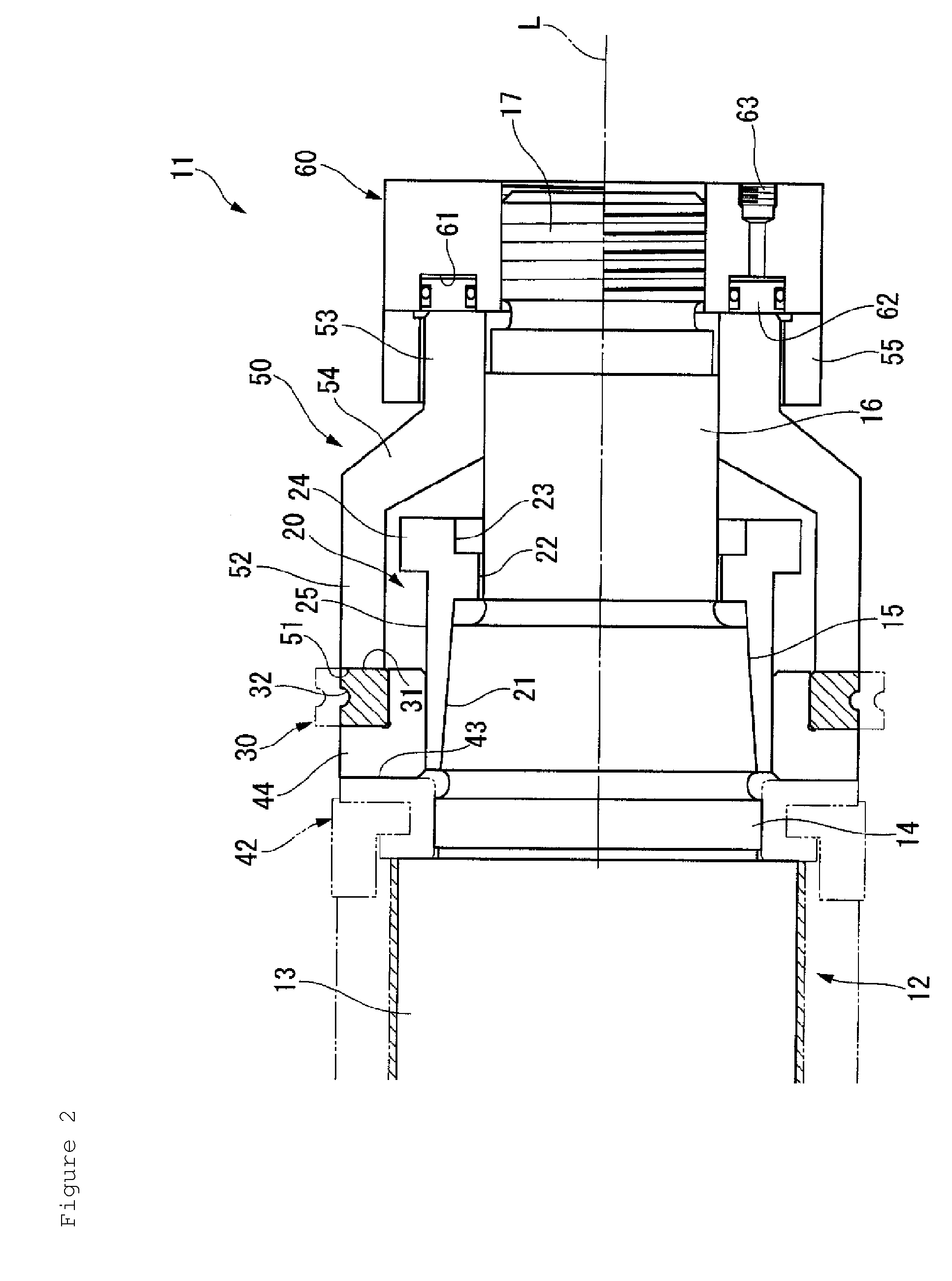
[0088]Next, FIG. 5 through FIG. 12 show the additional embodiments of the present invention, wherein portions that are in common with the previous embodiments shown in FIG. 1 through FIG. 4 are assigned the same symbols, and the explanations thereof are simplified. Aspects that are common to these embodiments include, first, that the inner circumferential support part is formed integrally with the sleeve member 20, the same as in the previous embodiment; namely, the tapered hole 21, which is capable of mating with the tapered part 15 of the shaft 12, and an inner circumferential support part 27, which is a constant diameter part and has an outer diameter that is constant and just slightly smaller than the inner diameter of the rolling ring 30, are formed coaxially in the sleeve member 20, the inner circumferential support part 27 is used to support the inner circumferential surface of the rolling ring 30 in the state wherein the sleeve member 20 is mated to the tapered part 15 so as...

first embodiment

[0090]Furthermore, in certain embodiments, the flange part 24 and the constant diameter part 25, the outer diameter of which is smaller than the projecting part (the inner circumferential support part), are not provided to the sleeve member 20 as in the first embodiment, and the sleeve member 20 has an L shaped cross section. In addition, the outer diameter of the side surface support part 28 is substantially the same as the discard outer diameter of the rolling ring 30; however, as shown in the drawing, it is slightly smaller. Furthermore, in some embodiments, multiple (2) forming grooves 32 are formed in the rolling ring 30 lined up in the directions of the axis L; in contrast, other embodiments, only one forming groove 32 is formed, the same as in the initial embodiments.

[0091]In addition, another aspect common to certain embodiments is that, on the side where the side surface support part 28 is not integrally formed with the sleeve member 20, a ring shaped spacer 47 is formed th...

seventh embodiment

[0097]Next, the pressing nut 70 is screwed to the male thread part 17, and one end surface of the pressing nut 70 contacts the sleeve member 20 in certain embodiments and contacts the spacer 47, which juts out from the inner circumferential support part 27 toward the other end side, in an embodiment. In addition, a pressing ring 71 is disposed by loosely inserting it on the outer circumference of the pressing nut 70, and the hydraulic nut 60 is further screwed to the male thread part 17 from the other end side. Here, the pressing nut 70 is ring shaped with a square cross section and has an outer diameter that is larger than that of the inner circumferential support part 27 of the sleeve member 20 and smaller than that of the side surface support part 28, which is formed integrally with the sleeve member 20, and the spacer 47 that is in the seventh embodiment; furthermore, a female thread part 70A, which screws to the male thread part 17, is formed in the inner diameter part of the p...


PUM

PropertyMeasurementUnit
outer circumferenceaaaaaaaaaa
circumferenceaaaaaaaaaa
inner diameteraaaaaaaaaa

Abstract

The present invention provides a rolling roll that has a shaft, which rotates around an axis and has one end that is connected to an output shaft of a rolling mill, and is configured such that a tubular sleeve member is mounted to a portion of the shaft on the side of another end, and a rolling ring, which is formed from a hard material, is fixed to an outer circumference of the sleeve member, wherein an inner circumferential support part is disposed on an outer circumferential side of the sleeve member; the rolling ring is supported by the sleeve member via the inner circumferential support part; a pressing member and a pressing mechanism are disposed on the other end side of the rolling ring; and the pressing member and the pressing mechanism press the rolling ring toward the one end side, thereby fixing it.

Description

CROSS-REFERENCE TO RELATED APPLICATION[0001]The present application claims priority from U.S. Provisional Application No. 61 / 051,049, filed May 7, 2008, and is hereby incorporated by reference in its entirety herein.FIELD OF THE INVENTION[0002]The present invention relates to: a so-called cantilevered rolling roll that is configured by fixing a rolling ring, which is made of a hard material, to an outer circumference of a shaft, one end of which is connected to an output shaft of a rolling mill; the rolling ring that constitutes the rolling roll; the rolling mill, which is provided with the rolling roll; and a method of assembling the rolling roll.BACKGROUND[0003]Generally, when bars and wires of, for example, metal are produced continuously, a process is widely adopted wherein rolling rolls, the outer circumferential surfaces of which have forming grooves formed therein, are used to continuously roll a metal material. To perform such rolling, so-called cantilevered rolling rolls ar...

Claims


Application Information

Patent Timeline
Patent Type & Authority Applications(United States)
IPC IPC(8): B21B27/02F16C13/00B21B35/00B21K1/02
CPCB21B27/035Y10T29/49552F16C13/00
Inventor OGURA, EIJIYURI, KOICHIFUKUDA, TSUTOMUTAKATSUKI, MITSUHIRO
Owner MITSUBISHI MATERIALS CORP
Why Eureka
Try Eureka