Control device

Inactive Publication Date: 2009-11-12
DAIKIN IND LTD
View PDF7 Cites 4 Cited by
  • Summary
  • Abstract
  • Description
  • Claims
  • Application Information

AI Technical Summary

Benefits of technology

[0018]In the control device according to the first aspect of the present invention, at the time of occurrence of an error of the air conditioner, it is easy to determine whether the error occurred due to multiple factors or due to external factors. Further, even if there is no error, if an indication of occurrence of an error is detected, it is possible to perform maintenance in advance.
[0019]In the control device according to the second aspect of the present invention, the microcomputer sequentially updates, from oldest to new, the operation information of the air conditioner stored in the memory. Accordingly, the size of the memory capacity to be used is prevented from becoming large.
[0020]In the control device according to the third aspect of the present invention, the microcomputer causes the memory to store the time series of ambient temperature in case of occurrence of an error in the air conditioner. Accordingly, it is possible to estimate a change in the behavior of electronic components associated with a temperature change, and this simplifies the narrowing down of error factors.
[0021]In the control device according to the fourth aspect of the present invention, the microcomputer causes the memory to store the time series of the reception error occurrence rate in case of occurrence of an error in the air conditioner. This simplifies the narrowing down of factors at the time of occurrence of an error in the signal transmission system.
[0022]In the control device according to the fifth aspect of the present invention, memory contents will not be lost even if the power supply is interrupted.
[0023]In the control device according to the sixth aspect of the present invention, the service provider can examine the need for maintenance of the air conditioner and, if needed, can visit the air conditioner installation site with equipment necessary for maintenance provided in advance. Accordingly, the maintenance workability is improved.

Problems solved by technology

However, with the method described in Patent Document 1, because the information provided is the operation information at the time of occurrence of an error, it is insufficient to perform detailed factor analysis.

Method used


Image

  • Control device
  • Control device
  • Control device

Examples


Embodiment Construction

[0038]

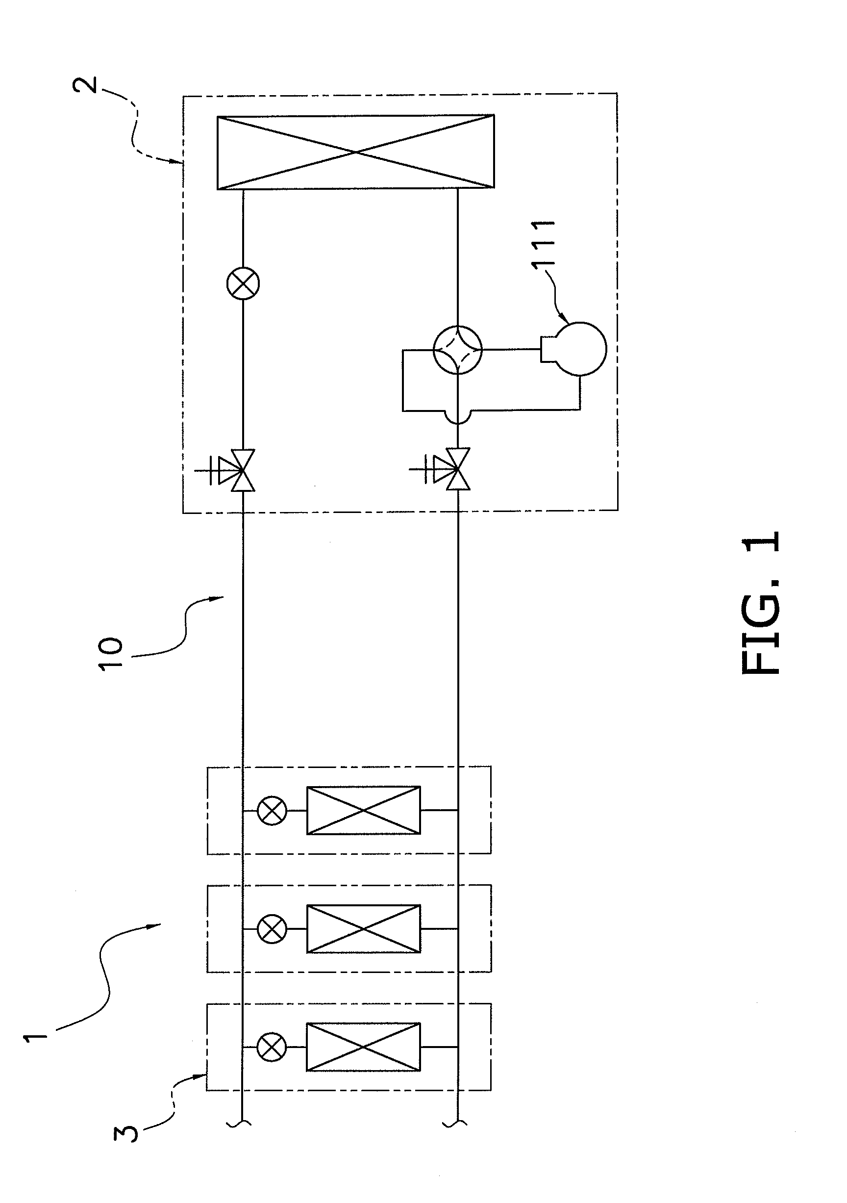
[0039]FIG. 1 is a configuration diagram of an air conditioner. An air conditioner 1 is a multi-type air conditioner for a building, in which a plurality of air conditioner indoor units 3 are connected in parallel to one or a plurality of air conditioner outdoor units 2, and a refrigerant circuit 10 is formed by the interconnection of devices such as a compressor 111 and the like such that the refrigerant can circulate therethrough.

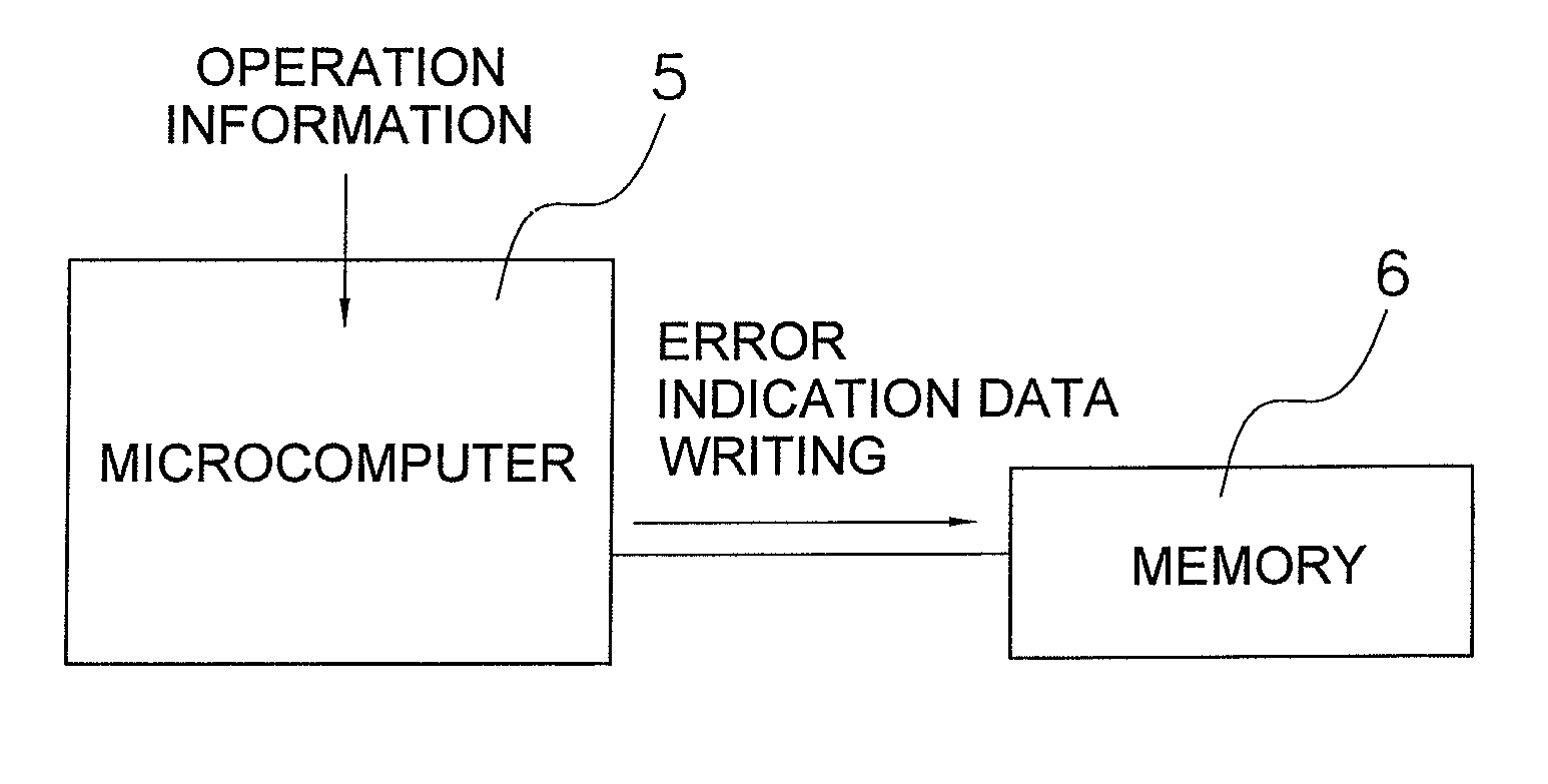
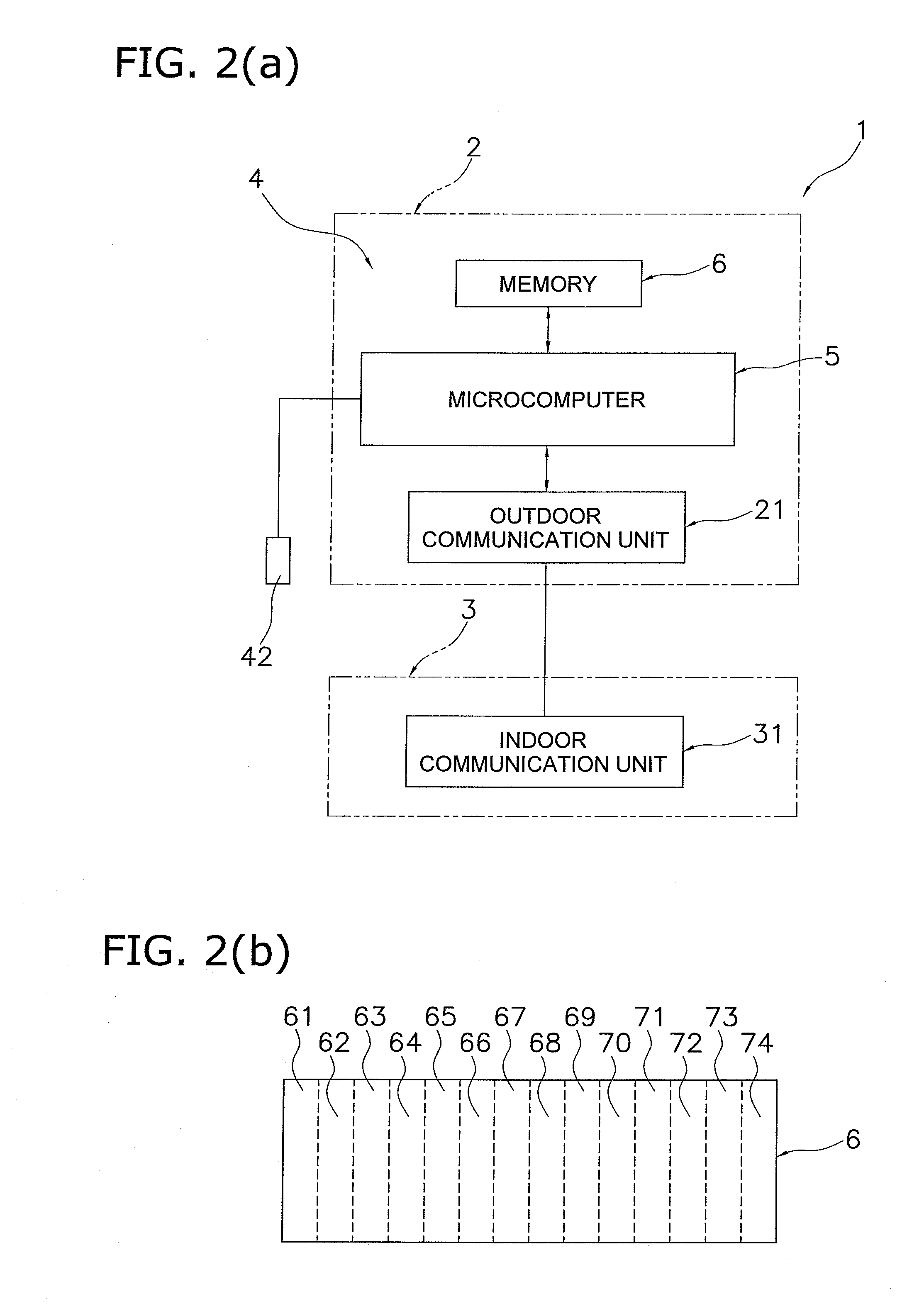
[0040]FIG. 2(a) is a block diagram of a control device according to the present embodiment, and FIG. 2(b) is an enlarged view of a memory. Each air conditioner outdoor unit 2 has an outdoor communication unit 21 and each air conditioner indoor unit 3 has an indoor communication unit 31, and these communication units 21 and 31 are capable of transmitting and receiving signals with each other. A control device 4 is equipped with a microcomputer 5, a memory 6, and the outdoor communication unit 21. The microcomputer 5 causes a signal to be transmitted a...


PUM


Abstract

A control device is configured to control an air conditioner that includes an air conditioner outdoor unit and an air conditioner indoor unit. The control device includes a microcomputer and a storage element. The microcomputer causes a signal to be transmitted and received between an outdoor communication unit of the air conditioner outdoor unit and an indoor communication unit of the air conditioner indoor unit. The storage element stores specific information in response to command from the microcomputer. The microcomputer causes the storage element to store operation information including a state of transmission and reception of the signal of the air conditioner at a constant time interval.

Description

TECHNICAL FIELD[0001]The present invention relates to a control device of an air conditioner.BACKGROUND ART[0002]In order to simplify factor analysis when an error occurs in an air conditioner, a conventional air conditioner employs a method in which operation information at the time of occurrence of an error is stored in a memory (for example, see Patent Document 1).[0003]<Patent Document 1> JP-A Publication No. 2004-156829DISCLOSURE OF THE INVENTIONObject to be Achieved by the Invention[0004]However, with the method described in Patent Document 1, because the information provided is the operation information at the time of occurrence of an error, it is insufficient to perform detailed factor analysis.[0005]An object of the present invention is to provide, in case of occurrence of an error in an air conditioner, a control device configured to store information necessary to analyze factors contributing to the error.Means to Achieve the Object[0006]A control device according to...

Claims


Application Information

Patent Timeline
IPC IPC(8): G05B15/00
CPCF24F11/0009F24F2011/0067F24F2011/0013F24F11/30F24F2110/12F24F11/54F24F11/64F24F11/38
Inventor SARUWATARI, HIROTAKAMATSUURA, HIROYUKIHAYASHI, MARIO
Owner DAIKIN IND LTD
Why Eureka
Try Eureka