Acceleration sensor having a surrounding seismic mass

a technology of acceleration sensor and surrounding seismic mass, which is applied in the direction of acceleration measurement using interia force, turn-sensitive devices, instruments, etc., can solve the problems of reducing affecting the accuracy of the measured capacitance, and causing mechanical stress in the substrate itself. , to achieve the effect of more recesses, strong against deformation, and stable against deformation

Inactive Publication Date: 2009-11-19
ROBERT BOSCH GMBH
View PDF6 Cites 26 Cited by
  • Summary
  • Abstract
  • Description
  • Claims
  • Application Information

AI Technical Summary

Benefits of technology

[0013]An example embodiment of the present invention provides that the sensor is designed as a linear acceleration sensor having at least one measuring axis. The suspension is advantageously designed as a beam in whose longitudinal direction the measuring axis is situated. It is also advantageous that the seismic mass surrounds the suspension in the shape of a closed ring. The seismic mass may thus be designed to be particularly sturdy against deformations. It is advantageous that the recesses have the shape of a closed ring. The recesses, whose edge areas form mobile capacitive electrodes, are thus particularly sturdy against deformations. The capacitive electrodes are advantageously provided individually anchored on the substrate. One advantageous embodiment of the present invention provides that two electrodes are situated in each recess. Capacitor structures which are properly shielded outward may thus be advantageously created between the corresponding electrode and the edge area of the recess opposite thereto. An example embodiment of the present invention provides that one electrode is situated in each recess. This arrangement is compact, so that advantageously smaller and thus more recesses are provided in the seismic mass, which increases the displayable capacitance and thus the measuring accuracy of the sensor.

Problems solved by technology

Stresses of this type may, however, also occur because the suspension or the seismic mass were manufactured already having internal stresses.
In addition, mechanical stresses may be caused in the substrate itself due to the manufacturing process, for example, by soldering or gluing, or capping.
For example, in the case of capacitive acceleration sensors, a zero point error occurs for the measured capacitance due to a change in the distance of the mobile electrodes to the fixed electrodes.

Method used


Image

  • Acceleration sensor having a surrounding seismic mass
  • Acceleration sensor having a surrounding seismic mass
  • Acceleration sensor having a surrounding seismic mass

Examples


Embodiment Construction

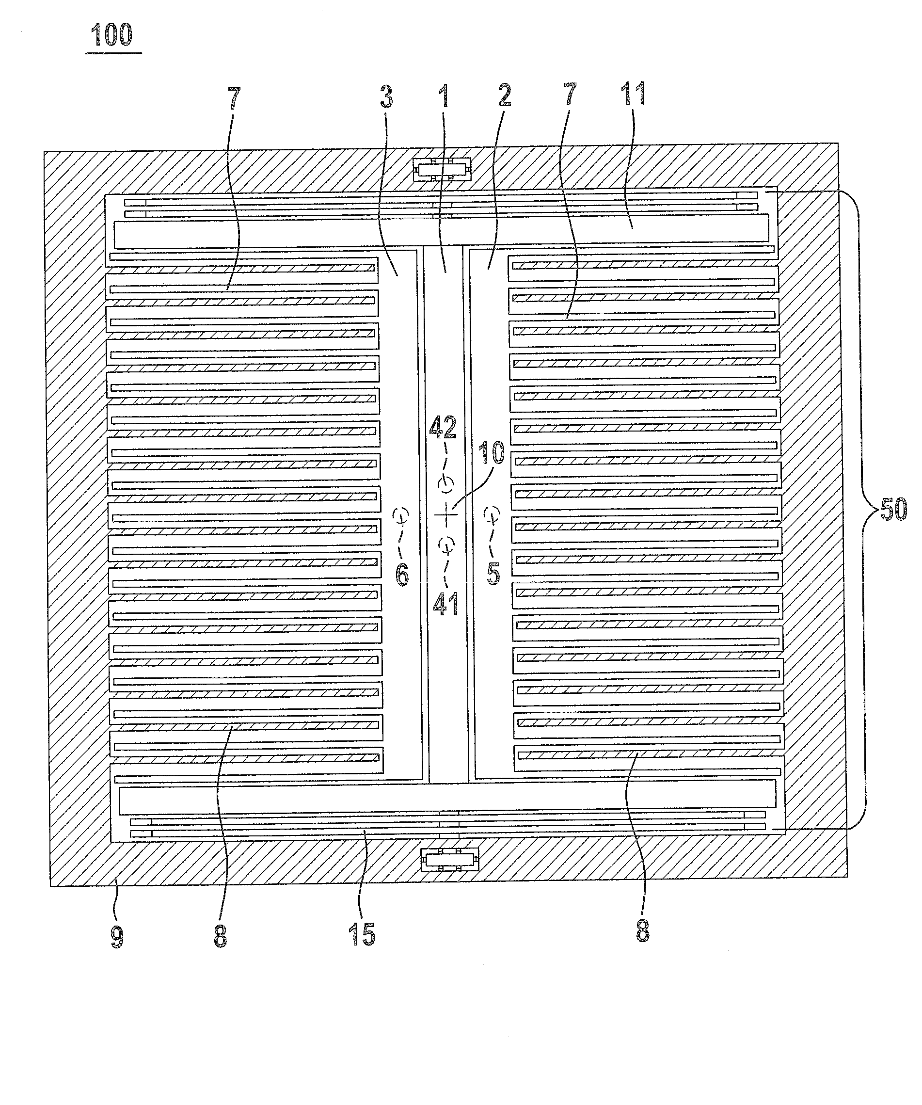
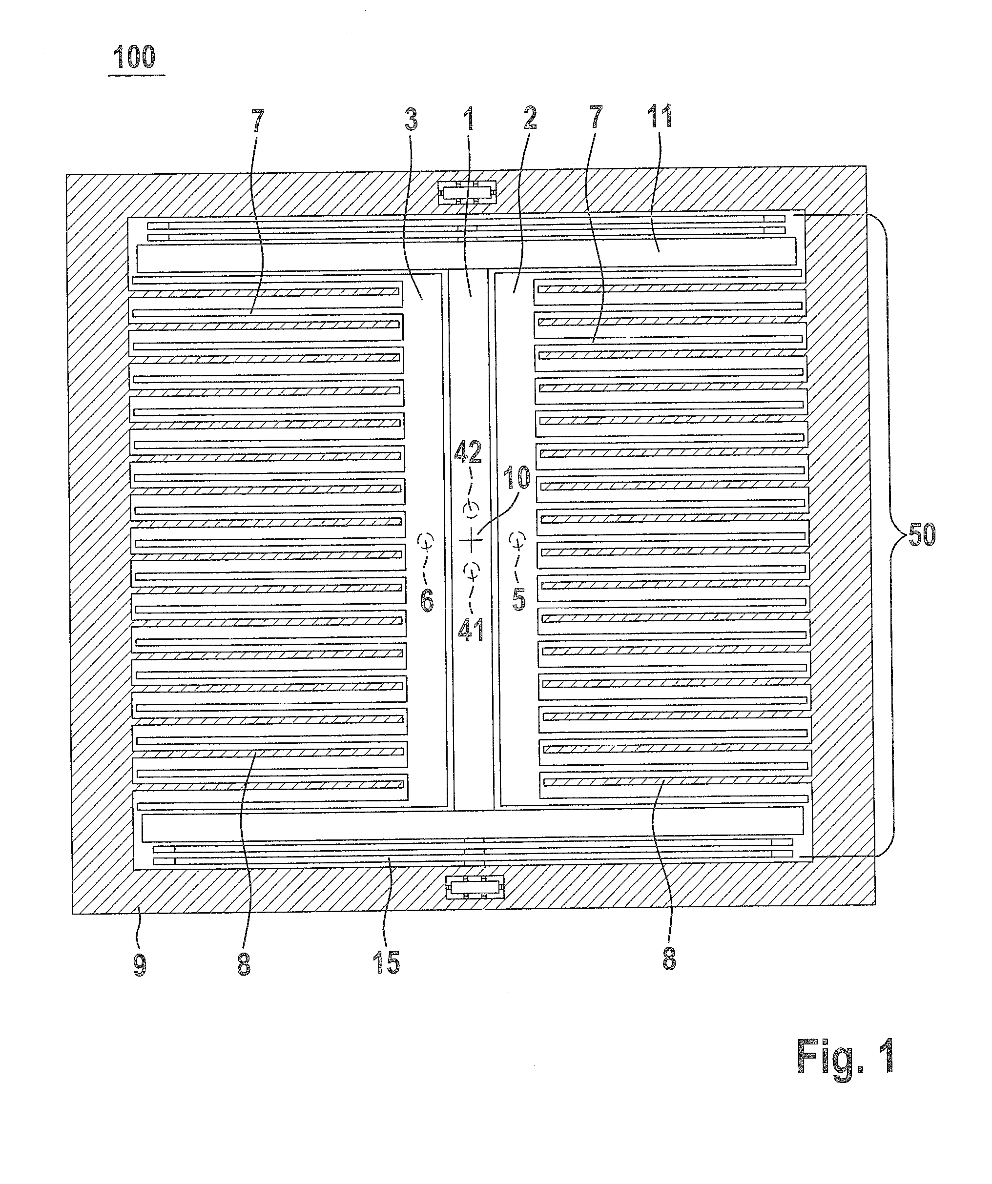
[0018]FIG. 1 shows an acceleration sensor as described in German patent application document DE 10 2007 047 592, which is not deemed to be a prior publication with respect to the present application. The acceleration sensor has a substrate 100, a seismic mass 9, a suspension 50 having two anchors 41 and 42 near the center, a suspension beam 1, and spring elements 15. Mass center of gravity 10 (also often referred to as the surface center of gravity or also the central axis) of seismic mass 9, or its projection in top view, runs through suspension beam 1. The two anchors 41 and 42 are not situated on mass center of gravity 10, but at a short distance adjacent thereto. They are situated under the suspension beam and are therefore illustrated by a dashed line. The two anchors 41 and 42 anchor suspension beam 1 on substrate 100. In the acceleration sensor illustrated, mass center of gravity 10 is located between anchors 41 and 42. Cross beams 11 and thereon, in turn, spring elements 15 ...


PUM


Abstract

A micromechanical acceleration sensor has a substrate, a suspension, a seismic mass, and stationary capacitive electrodes, which seismic mass is suspended over the substrate with the aid of the suspension. The seismic mass has a mass center of gravity, and the suspension has at least two anchors on the substrate, the at least two anchors being situated next to the mass center of gravity at a distance which is small compared to a horizontal extension of the seismic mass. The stationary capacitive electrodes are provided in recesses of the seismic mass. The seismic mass directly surrounds the suspension.

Description

BACKGROUND OF THE INVENTION[0001]1. Field of the Invention[0002]The present invention relates to a micromechanical acceleration sensor having a substrate, a suspension, a seismic mass, and stationary capacitive electrodes, which seismic mass is suspended over the substrate with the help of the suspension.[0003]2. Description of Related Art[0004]A sensor of the type described above is disclosed in German Patent Application document DE 10 2007 047 592, which is not deemed to be a prior publication with respect to the present application. The movable electrodes are situated here on the internal edge of the seismic mass. The stationary capacitive electrodes are situated with the help of shared suspension bars directly in the vicinity of the central suspension bar of the seismic mass.[0005]If the substrate is made of a material that is different from that of the seismic mass and its suspension, mechanical stresses between the substrate and the suspension or the seismic mass may occur due...

Claims


Application Information

Patent Timeline
Patent Type & Authority Applications(United States)
IPC IPC(8): G01C19/56G01P15/125
CPCG01P2015/0814G01P15/125
Inventor REHLE, DIRK
Owner ROBERT BOSCH GMBH
Why Eureka
Try Eureka