Integrated rotary union and hub cap

a technology of rotary union and hub cap, which is applied in the direction of tire measurement, vehicle components, transportation and packaging, etc., can solve the problems of affecting the performance of the tire, difficulty in manually checking and maintaining the optimum tire pressure for each and every tire, and air leakage from the tire, so as to reduce the misalignment of components and facilitate installation.

Active Publication Date: 2009-11-19
HENDRICKSON USA L L C
View PDF39 Cites 85 Cited by
  • Summary
  • Abstract
  • Description
  • Claims
  • Application Information

AI Technical Summary

Benefits of technology

[0014]An objective of the present invention is to provide a rotary union for a tire inflation system that is easier to install, thereby reducing misalignment of components associated with the rotary union.

Problems solved by technology

Therefore, the wheel end assembly must be sealed to prevent leakage of the lubricant, and also to prevent contaminants from entering the assembly, both of which could be detrimental to its performance.
However, it is well known that air may leak from a tire, usually in a gradual manner, but sometimes rapidly if there is a problem with the tire, such as a defect or a puncture caused by a road hazard.
The large number of tires on any given trailer setup makes it difficult to manually check and maintain the optimum tire pressure for each and every tire.
This difficulty is compounded by the fact that multiple trailers in a fleet may be located at a site for an extended period of time, during which the tire pressure might not be checked.
Such operation may increase the chance of failure of a tire in service or may lead to less efficient operation of the vehicle as compared to operation with tires in an optimum inflation range.
Moreover, should a tire develop a leak, for example, as a result of striking a road hazard, the tire could fail if the leak continues unabated as the vehicle travels over-the-road.
The potential for tire failure often is more pronounced in vehicles such as tractor-trailers that travel for long distances and / or extended periods of time.
The elbow or tee fitting is attached to the exterior of the hub cap, which increases the possibility that the fitting can be damaged.
Such damage may undesirably compromise the integrity of the tire inflation system, and / or may at least create a need to replace the fitting and other components of the system.
To reduce the possibility of such damage, a guard typically is installed to protect the elbow or tee fitting, which results in increased cost and weight, and adds an additional component that must be removed and replaced when servicing the components of the wheel end assembly or the tire inflation system.
During installation of such exterior rotary unions, the inboardly-extending air tube can be misaligned, resulting in premature wear of the bearings of the rotary union, which undesirably shortens the life of the rotary union.
In addition, the mounting of the rotary union on the exterior of the hub cap causes the rotary union itself to extend outboardly of the hub cap, thereby increasing the possibility that the rotary union may undesirably be damaged and require replacement.

Method used


Image

  • Integrated rotary union and hub cap
  • Integrated rotary union and hub cap
  • Integrated rotary union and hub cap

Examples


first embodiment

[0039]With particular reference to FIGS. 5 and 6, first embodiment integrated rotary union and hub cap is indicated generally at 100. Integrated rotary union and hub cap 100 includes a rotary union 102 and a hub cap 104. Hub cap 104 includes a cylindrical sidewall 106, and an outboard wall 108 integrally formed with the outboard end of the side wall and extending generally perpendicular to the sidewall. Preferably, a radially-extending flange 110 is formed on the inboard end of sidewall 106, and is formed with a plurality of bolt openings (not shown) to enable bolts to secure hub cap 104 to the outboard end of wheel hub 28. In this manner, hub cap 104 defines an interior compartment 112. It is to be understood that means known to those skilled in the art other than bolts may be used to secure hub cap 104 to wheel hub 28, such as a threaded connection between the hub cap and wheel hub, other types of mechanical fasteners, and / or a press fit.

[0040]A cylindrical boss structure 114 is f...

second embodiment

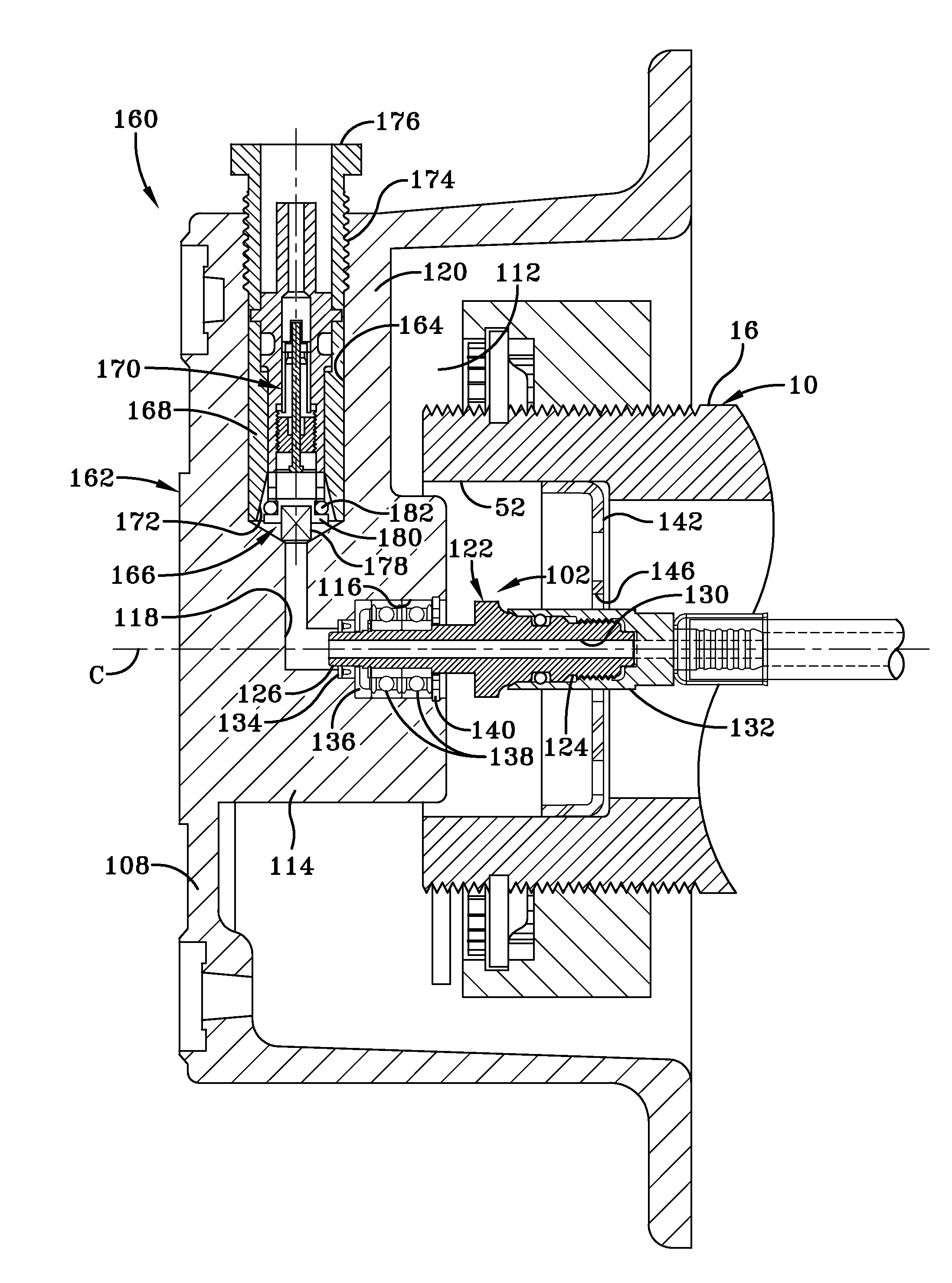
[0051]In this manner, air passes through tire inflation system conduit 44 in axle bore 48, through central bore 130 formed in rotary union stem 122, through aligned air passage 118, through poppet valve assembly 166 and Schrader valve assembly 170 disposed in bore 164, and through the tire hoses. As a result, second embodiment integrated rotary union and hub cap 160 eliminates the need to protect an elbow or tee fitting with a guard, since no components other than the tire hose(s) are exposed outside of the exterior of hub cap 162. Elimination of such a guard reduces cost and weight, and also reduces the components that need to be removed and re-installed when servicing the system.

[0052]Turning now to FIG. 8, third embodiment integrated rotary union and hub cap is indicated generally at 210. Third embodiment integrated rotary union and hub cap 210 is similar to second embodiment integrated rotary union and hub cap 160, with the exception that the third embodiment integrated rotary u...

third embodiment

[0053 integrated rotary union and hub cap 210 includes a rotary union 212 and a hub cap 214. Hub cap 214 includes a cylindrical sidewall 216, and an outboard wall 218 integrally formed with the outboard end of the side wall and extending generally perpendicular to the sidewall. A radially-extending flange 220 is formed on the inboard end of side wall 216, and is formed with a plurality of bolt openings (not shown) to enable bolts to secure hub cap 214 to the outboard end of wheel hub 28 (FIG. 5). In this manner, hub cap 214 defines an interior compartment 222.

[0054]Hub cap outboard wall 218 includes an inboard surface 224, and a cylindrical cavity 226 is formed in the inboard surface in alignment with axial centerline C of axle spindle 16 (FIG. 6). Cylindrical cavity 226 is in fluid communication with an air passage 228 that is formed in hub cap outboard wall 218, as will be described in greater detail below. Rotary union 212 protrudes into interior compartment 222 of hub cap 214, a...


PUM


Abstract

A rotary union is integrated into the interior of a heavy-duty vehicle hub cap. The hub cap includes a cylindrical sidewall, and an outboard wall that is integrally formed with an outboard end of the sidewall, and which extends generally perpendicular to the sidewall. The hub cap also includes a radially-extending flange that is formed on an inboard end of the sidewall, which receives fasteners to mount the hub cap on a wheel hub. The sidewall and the outboard wall form an interior compartment in the hub cap, and a rotary union is mounted to the hub cap in the interior compartment. The rotary union is mounted on the inboard surface of the outboard wall of the hub cap and is in general axial alignment with an axial centerline of a wheel end assembly, providing fluid communication from a tire inflation system to the tires of the vehicle.

Description

CROSS-REFERENCE TO RELATED APPLICATIONS[0001]This application claims the benefit of U.S. Provisional Patent Application Ser. No. 61 / 053,757, which was filed on May 16, 2008.BACKGROUND OF THE INVENTION[0002]1. Technical Field[0003]The invention relates to the art of tire inflation systems for heavy-duty vehicles such as tractor-trailers or semi-trailers. More particularly, the invention relates to a rotary union for use in a tire inflation system for heavy-duty vehicles. Still more particularly, the invention is directed to a rotary union that is integrated into the interior of a hub cap of a wheel end assembly, which simplifies installation of the rotary union and reduces potential damage to the rotary union, thereby extending the life of the rotary union.[0004]2. Background Art[0005]Reference herein is made to tractor-trailers and semi-trailers by way of example, with the understanding that such reference applies to other heavy-duty vehicles, such as straight trucks. All tractor-tr...

Claims


Application Information

Patent Timeline
Patent Type & Authority Applications(United States)
IPC IPC(8): B60C23/10
CPCB60C23/003B60C23/00327B60C23/00345B60C23/00354B60C23/00363
Inventor PADULA, SANTOCERVANTEZ, JESSE W.
Owner HENDRICKSON USA L L C
Why Eureka
Try Eureka