Capacitive motion detection device and input device using the same

a technology of capacitive motion and input device, which is applied in the direction of instruments, computing, electric digital data processing, etc., can solve the problems of device vibration, limited space in which the method is used, and high cost of hardware, software and the like, and achieves the effect of simple configuration and few limitations

Active Publication Date: 2009-11-19
ALPS ALPINE CO LTD
View PDF16 Cites 41 Cited by
  • Summary
  • Abstract
  • Description
  • Claims
  • Application Information

AI Technical Summary

Benefits of technology

[0007]In view of the aforementioned problems, the present invention provides a capacitive motion detection device and an input device using the same. The capacitive motion detection device has a simple configuration, has few limitations regarding the operating environment, does not affect a device due to vibrations, and need not include a specific input device.

Problems solved by technology

However, in the method, in which a camera and image processing are used, the costs of hardware, software, and the like are high, and the space in which the method is used is limited because a specific space for capturing camera images needs to be prepared in advance.
When the hardware main body is moved, the device may be affected by vibrations.

Method used


Image

  • Capacitive motion detection device and input device using the same
  • Capacitive motion detection device and input device using the same
  • Capacitive motion detection device and input device using the same

Examples


Embodiment Construction

[0027]An embodiment of the present invention will now be described in detail with reference to the attached drawings.

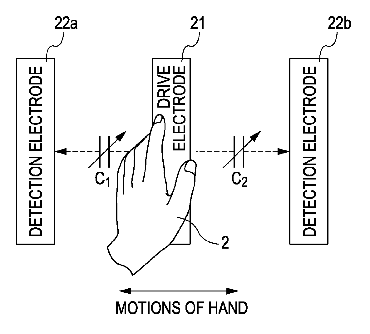
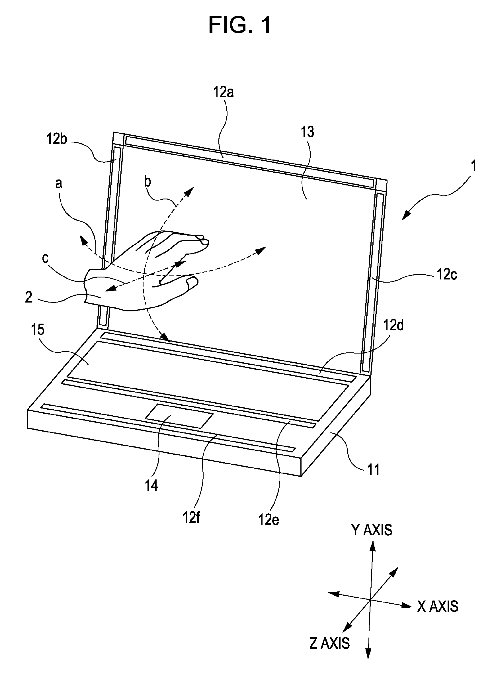
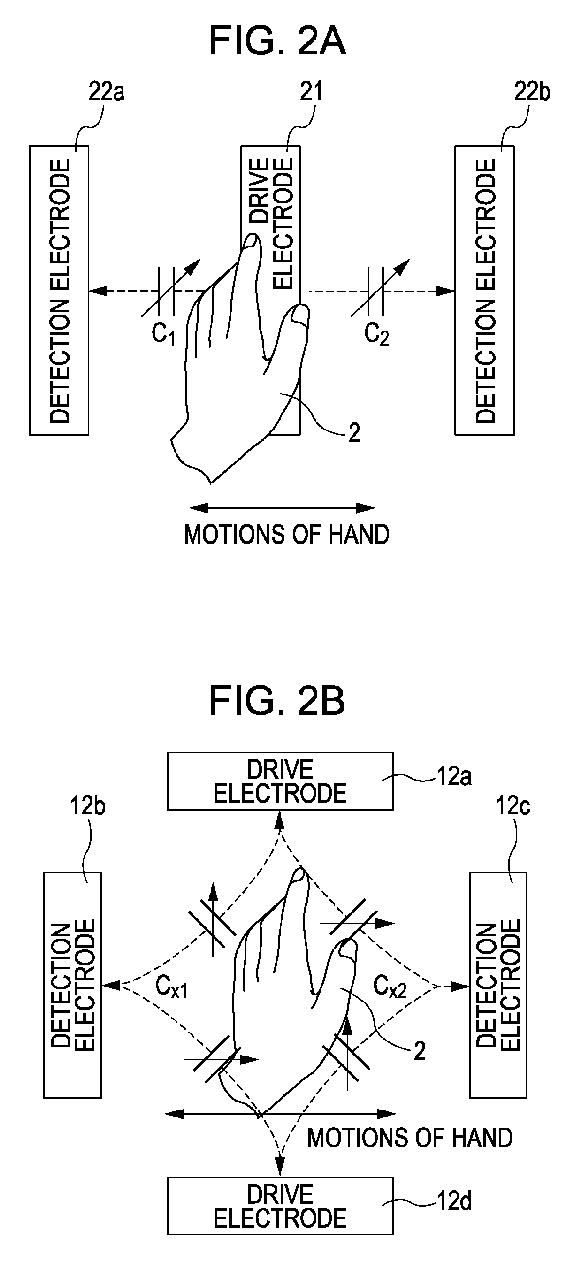
[0028]FIG. 1 shows a notebook personal computer (PC) according to the present invention serving as an input device. The notebook PC 1 includes a monitor 13 and a keyboard 15 that are different areas. At least one electrode of a detection electrode / drive electrode pair is provided in each of the areas. That is, the notebook PC 1 includes electrodes 12a, 12b, 12c, and 12d formed around the monitor 13, an electrode 12e formed opposite the electrode 12d with the keyboard 15 between the electrode 12e and the electrode 12d, and an electrode 12f formed opposite the electrode 12e with a glidepoint 14 between the electrode 12f and the electrode 12e. These electrodes are provided at individual detection positions for an area to be operated and constitute two or more detection electrode / drive electrode pairs in each of which a capacitance is formed between a detection electrode ...


PUM


Abstract

When a motion in the X-axis direction is detected, first electrodes are set as drive electrodes, and second electrodes are set as detection electrodes. A switching circuit performs switching so as to electrically connect a drive circuit to the first electrodes, electrically connect a first detection circuit to one of the second electrodes, and electrically connect a second detection circuit to the other second electrode. In a motion detection circuit in which connections are established in this manner, the drive circuit drives the drive electrodes, and then the position of an object to be detected in the X-axis direction is obtained from the difference between capacitances detected by the first and second detection circuits at this time.

Description

CLAIM OF PRIORITY[0001]This application claims benefit of the Japanese Patent Application No. 2007-021333 filed on Jan. 31, 2007, which is hereby incorporated by reference.BACKGROUND OF THE INVENTION[0002]1. Field of the Invention[0003]The present invention relates to a capacitive motion detection device detecting, by the use of capacitances, the motions of an object to be detected in an area to be operated and an input device using the same.[0004]2. Description of the Related Art[0005]Methods for detecting the motions of an object to be detected, such as a human body, include, for example, a method for detecting the motions of a person by capturing the images of the person and outputting the motions to a control unit in a personal computer (PC), using at least one camera and an image processing unit (for example, Japanese Unexamined Patent Application Publication No. 2001-87549). Moreover, the methods include a method for outputting the motions to a control unit in a PC by embeddin...

Claims


Application Information

Patent Timeline
Patent Type & Authority Applications(United States)
IPC IPC(8): G06F3/044G06F3/033G06F3/0346G06F3/041
CPCG06F3/044G06F3/0346G06F3/0446
Inventor OKI, TOSHIYUKI
Owner ALPS ALPINE CO LTD
Why Eureka
Try Eureka