
Image forming apparatus and maintenance method

a technology of image forming apparatus and maintenance method, which is applied in the direction of printing mechanism, printing, power drive mechanism, etc., can solve the problems of inability to carry out sufficient cleaning, inability to fix the recording medium stably, and inability to meet the requirements of high-speed printing methods, etc., to achieve the effect of sufficient space and time for discharging air and improving productivity

Inactive Publication Date: 2009-11-19
FUJIFILM CORP
View PDF2 Cites 79 Cited by
  • Summary
  • Abstract
  • Description
  • Claims
  • Application Information

AI Technical Summary

Benefits of technology

[0009]The present invention has been contrived in view of these circumstances, an object thereof being to provide an image forming apparatus and a maintenance method which achieve desirable maintenance of a conveyance member, which holds a recording medium by suction and conveys the recording medium.

Problems solved by technology

However, in fixing a recording medium in the vacuum suction device with no cleaning mechanism as in Japanese Patent Application Publication No. 10-175338, when ink mist, paper dust, or the like, becomes filled into the vacuum flow channels, it is not possible to fix the recording medium stably in position.
Further, paper dust and other dirt may adhere to the recording medium conveyance members in addition to ink.
However, due to the fact that the cleaning device is of a sliding type, the abrasion of the blade causes rapid wear when the conveyance speed is fast, and hence this method cannot be regarded as suitable for high-speed printing.
Moreover, as wearing of the blade progresses, there is a problem in that sufficient cleaning cannot be carried out.
Further, if cleaning using a blade is employed for a recording medium conveyance member (paper feed device) having holes arranged in the surface that holds the recording medium as in Japanese Patent Application Publication No. 10-175338, then although it is possible to remove the adhering material that is adhering to the surface holding the recording medium and the periphery of the holes, it is difficult to remove adhering material that has entered into the holes.

Method used


Image

  • Image forming apparatus and maintenance method
  • Image forming apparatus and maintenance method
  • Image forming apparatus and maintenance method

Examples


first embodiment

Description of Maintenance of Pressure Drum (Conveyance Drum): First Embodiment

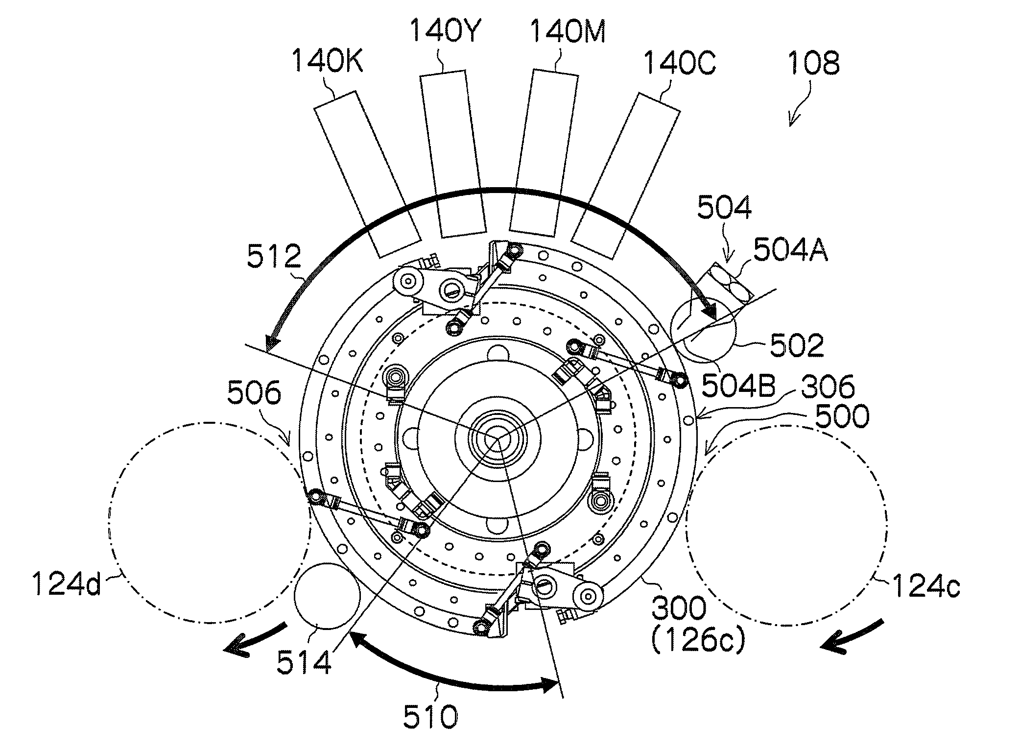
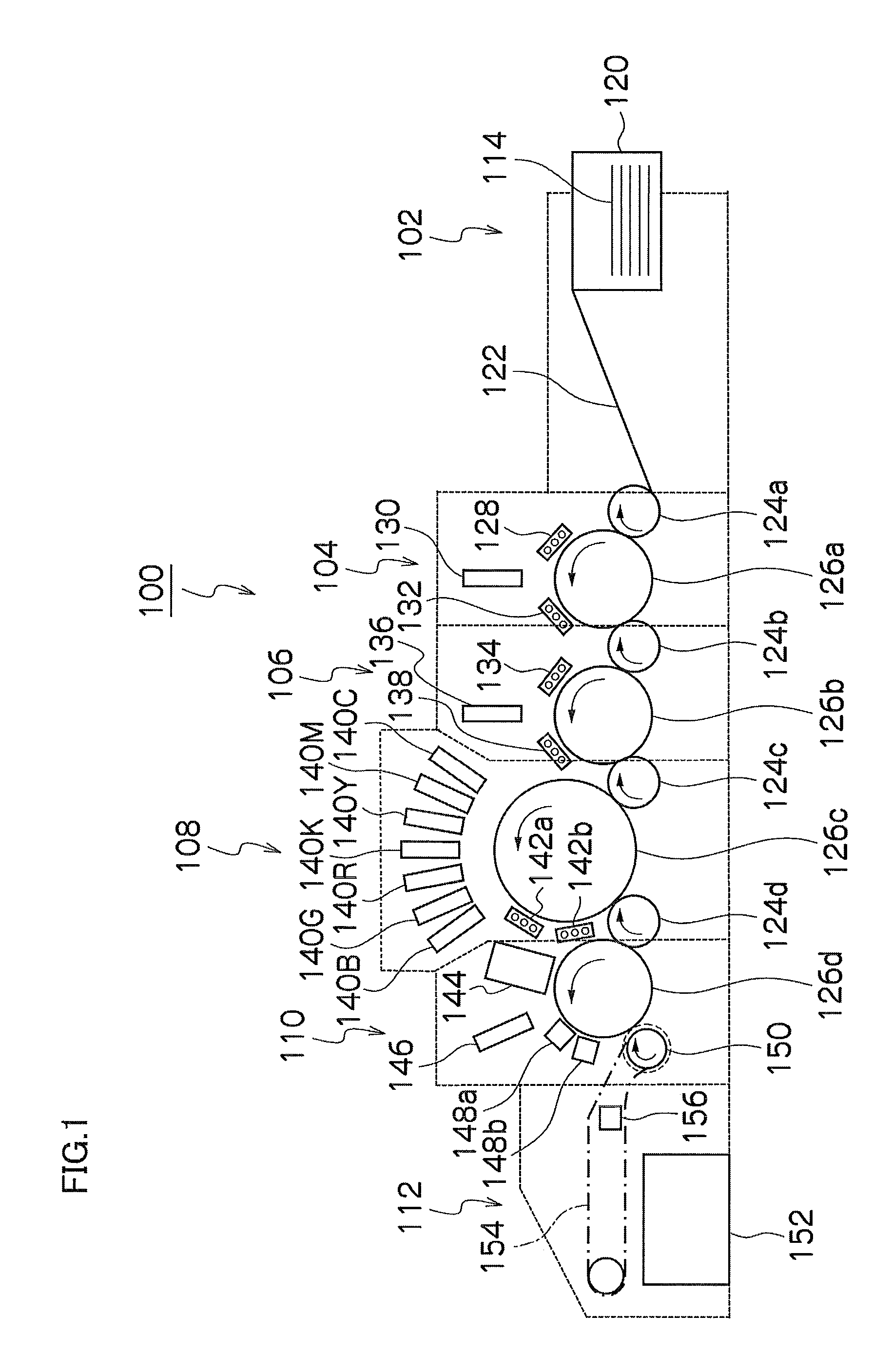
[0245]Next, the maintenance of the conveyance drum 300 will be described. As described above, after the recording medium has been transferred to the transfer drum 124d at the transfer position 506, when the conveyance drum 300 is rotated further and the recording medium holding region (see FIG. 7) reaches the position of a cleaning roller 514, which is disposed to the downstream side of the transfer position 506, then cleaning of the recording medium holding region is carried out by means of the cleaning roller 514.

[0246]The cleaning roller 514 is composed so as to rotate idly in accordance with the rotation of the conveyance drum 300, and is pressed against the outer circumferential surface 306 of the conveyance drum 300 with a prescribed pressure. Furthermore, when the conveyance drum 300 rotates and the recording medium holding region arrives at a blowing region 510, compressed air is supplied to the v...

second embodiment

Description of Maintenance of Pressure Drum (Conveyance Drum): Second Embodiment

[0264]Next, the maintenance of the conveyance drum 300 in an inkjet recording apparatus according to a second embodiment of the present invention will be described.

[0265]In the maintenance control of the conveyance drum 300 in the second embodiment, vacuum holding of the recording medium is carried out when printing (in image forming mode), and maintenance of the conveyance drum 300 is carried out when not printing (in maintenance mode). In other words, the flow channel from the conveyance drum 300 to the vacuum pump 520 is composed so as to be selectively connectable to the compressor 522, and the vacuum pump 520 and the compressor 522 are switched in such a manner that the suction sheet (see FIGS. 7 and 9) is suctioned when printing and compressed air is supplied to the suction sheet when not printing.

[0266]When continuously forming a plurality of images, during printing, holding of the recording mediu...


PUM


Abstract

The image forming apparatus includes: a recording medium conveyance device which includes air flow channels and a recording medium holding region on which a recording medium is held, a surface of the recording medium holding region having openings in connection with the air flow channels, the recording medium conveyance device conveying the recording medium in a prescribed conveyance direction while holding the recording medium on the recording medium holding region by suction; a suction device which performs air suction through the openings to perform holding of the recording medium on the recording medium holding region by suction when the recording medium is disposed on the recording medium holding region; an image forming device which performs image formation onto the recording medium held on the recording medium holding region by the suction device; a discharging device which performs air discharge through the openings when no recording medium is disposed on the recording medium holding region; and an air switching device which performs switching between the air suction and the air discharge.

Description

BACKGROUND OF THE INVENTION[0001]1. Field of the Invention[0002]The present invention relates to an image forming apparatus and a maintenance method, and more particularly to maintenance technology for conveyance members which hold and convey a recording medium.[0003]2. Description of the Related Art[0004]As a general image forming apparatus, it is suitable to use an inkjet recording apparatus, which forms a desired image on a recording medium by ejecting and depositing a plurality of colors of inks onto the recording medium from a plurality of nozzles provided in an inkjet head. In the inkjet recording apparatus, the recording medium is held and conveyed by, for example, a drum conveyance method or a belt conveyance method. In the drum conveyance method, the recording medium is held on the outer circumferential surface of a conveyance member having a drum shape, and the recording medium is conveyed with rotation of the drum. In the belt conveyance method, the recording medium is he...

Claims


Application Information

Patent Timeline
IPC IPC(8): B41J29/38B41J2/01
CPCB41J29/38B41J2025/008
Inventor FUKUI, TAKASHI
Owner FUJIFILM CORP
Learn More