Image processing Method

a processing method and image technology, applied in image enhancement, distance measurement, instruments, etc., can solve the problems of high cost, time-consuming installation of photographing equipment, and complex fabrication of cameras, and achieve the effect of sacrificing the resolution of cameras

Inactive Publication Date: 2009-11-19
KK TOSHIBA
View PDF14 Cites 94 Cited by
  • Summary
  • Abstract
  • Description
  • Claims
  • Application Information

AI Technical Summary

Benefits of technology

[0137]As has been described above, with the image processing method according to the first embodiment of the present invention, compared to the prior art, the depth of a scene can be estimated by a simpler method.
[0138]According to the method of the present embodiment, a three-color filter of RGB is disposed at the aperture of the camera, and a scene is photographed. Thereby, images, which are substantially photographed from three view points, can be obtained with respect to one scene. In the present method, it should suffice if the filter is disposed and photographing is performed. There is no need to modify image sensors and photographing components other than the camera lens. Therefore, a plurality of images, as viewed from a plurality of view points, can be obtained from one RGB image.
[0139]Moreover, compared to the method disclosed in document 1, which has been described in the section of the background art, the resolution of the camera is sacrificed. Specifically, in the method of document 1, the micro-lens array is disposed at the image pickup unit so that a plurality of pixels may correspond to the individual micro-lenses. The respective micro-lenses refract light which is incident from a plurality of directions, and the light is recorded on the individual pixels. For example, i...

Problems solved by technology

In these methods, however, there are such problems that the scale of the photographing apparatus increases, the cost is high, and the installation of the photographing apparatus is time-consuming.
However, in this method, the fabrication of the camera becomes very complex.
Moreover, there is such a problem that the resolution of each image deteriorates since a plurality of images are included in a single image.
The...

Method used


Image

  • Image processing Method
  • Image processing Method
  • Image processing Method

Examples


first embodiment

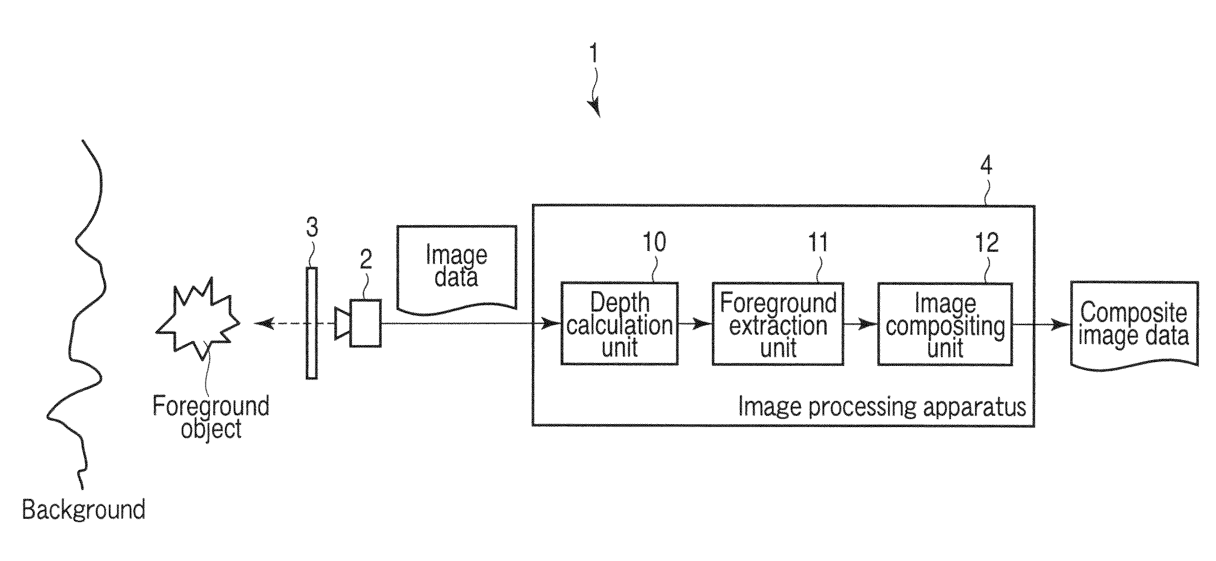
[0035]An image processing method according to a first embodiment of the present invention will now be described with reference to FIG. 1. FIG. 1 is a block diagram of an image processing system according to the present embodiment.

[0036]As shown in FIG. 1, the image processing system 1 includes a camera 2, a filter 3 and an image processing apparatus 4. The camera 2 photographs an object of photography (a foreground object and a background), and outputs acquired image data to the image processing apparatus 4.

[0037]The image processing apparatus 4 includes a depth calculation unit 10, a foreground extraction unit 11 and an image compositing unit 12. The depth calculation unit 10 calculates the depth in a photographed image by using the image data that is delivered from the camera 2. On the basis of the magnitude of the depth that is calculated by the depth calculation unit 10, the foreground extraction unit 11 extracts a foreground corresponding to the foreground object in the photogr...

second embodiment

[0145]Next, an image processing method according to a second embodiment of the present invention is described. The present embodiment relates to the measure at the time of using the stereo matching method, which has been described in connection with the first embodiment. In the description below, only the points different from the first embodiment are explained.

[0146]In the first embodiment, the error eline (x,y; d), which is expressed by the equation (8), is used as the measure of the stereo matching method. However, the following measures may be used in place of the eline (x,y; d).

example 1

OF OTHER MEASURES

[0147]The straight line 1 (see FIG. 9) in the three-dimensional color space of RGB is also a straight line when the straight line 1 is projected on the RG plane, GB plane and BR plane. Consideration is now given to a correlation coefficient which measures the linear relationship between two arbitrary color components. If the correlation coefficient between the R component and G component is denoted by Crg, the correlation coefficient between the G component and B component is Cgb and the correlation coefficient between the B component and R component is Cbr, the Crg, Cgb and Cbr are expressed by the following equations (16):

Crg=cov(Ir,Ig) / √{square root over ((var(Ir)var(Ig)))}{square root over ((var(Ir)var(Ig)))}

Cgb=cov(Ig,Ib) / √{square root over ((var(Ig)var(Ib)))}{square root over ((var(Ig)var(Ib)))}

Cbr=cov(Ib,Ir) / √{square root over ((var(Ib)var(Ir)))}{square root over ((var(Ib)var(Ir)))}  (16)

where −1≦Crg≦1, −1≦Cgb≦1, and −1≦Cbr≦1. It is indicated that as the valu...


PUM


Abstract

An image processing method includes photographing an object by a camera via a filter, separating image data, which is obtained by photographing by the camera, into a red component, a green component and a blue component, determining a relationship of correspondency between pixels in the red component, the green component and the blue component, with reference to departure of pixel values in the red component, the green component and the blue component from a linear color model in a three-dimensional color space, and finding a depth of each of the pixels in the image data in accordance with positional displacement amounts of the corresponding pixels of the red component, the green component and the blue component. The image processing method further includes processing the image data in accordance with the depth.

Description

CROSS-REFERENCE TO RELATED APPLICATIONS[0001]This application is based upon and claims the benefit of priority from prior Japanese Patent Application No. 2008-130005, filed May 16, 2008, the entire contents of which are incorporated herein by reference.BACKGROUND OF THE INVENTION[0002]1. Field of the Invention[0003]The present invention relates to an image processing method. The invention relates more particularly to a method of estimating the depth of a scene and a method of extracting a foreground of the scene in an image processing system.[0004]2. Description of the Related Art[0005]Conventionally, there are known various methods of estimating the depth of a scene, as image processing methods in image processing systems. Such methods include, for instance, a method in which a plurality of images of an object of photography are acquired by varying the pattern of light by means of, e.g. a projector, and a method in which an object is photographed from a plurality of view points by ...

Claims


Application Information

Patent Timeline
IPC IPC(8): H04N5/335G06K9/34G06K9/40G01C3/06G06T1/00
CPCG06K9/00201G06T7/0051H04N9/045G06T2207/10024H04N5/23229G06T2207/10012G06T7/50G06V20/64H04N23/60H04N23/80H04N23/843H04N25/11
Inventor BANDO, YOSUKENISHITA, TOMOYUKI
Owner KK TOSHIBA
Why Eureka
Try Eureka