Component holding device

Active Publication Date: 2009-11-19
JTEKT CORP
View PDF6 Cites 8 Cited by
  • Summary
  • Abstract
  • Description
  • Claims
  • Application Information

AI Technical Summary

Benefits of technology

[0008]An object of the present invention is to provide a component holding device that discharges leaked gas such as hydrogen gas to the outside air and that effectively prevents the gas from remaining in the component holding device.
[0014]In the above aspect, a protective cover that protects the resistance member may be disposed in at least one of the component holding section and the fixing member. Accordingly, protection of the resistance member can be enhanced. The protective cover may be integrated with the component holding section or the fixing member, or may be a separate unit. Also, a protective cover that covers the fixing member may be provided. In this case, since the fixing member is covered by the protective cover, protective performance of the resistance member can also be enhanced. The protective cover may be an integrated unit with the component holding section or the fixing member, or may be a separate unit.
[0020]According to the aspect of the present invention, it is possible to provide a component holding device that effectively prevents gas leaked in the gas residual section in the first hole of the fixing member from remaining in the gas residual section. The component holding device is especially suitable when the gas is flammable or corrosive.

Problems solved by technology

As described above, since the component holding section is sealed by the sealing section, discharge of leaked gas to the outside air is limited by the scaling section.

Method used


Image

  • Component holding device
  • Component holding device
  • Component holding device

Examples


first embodiment

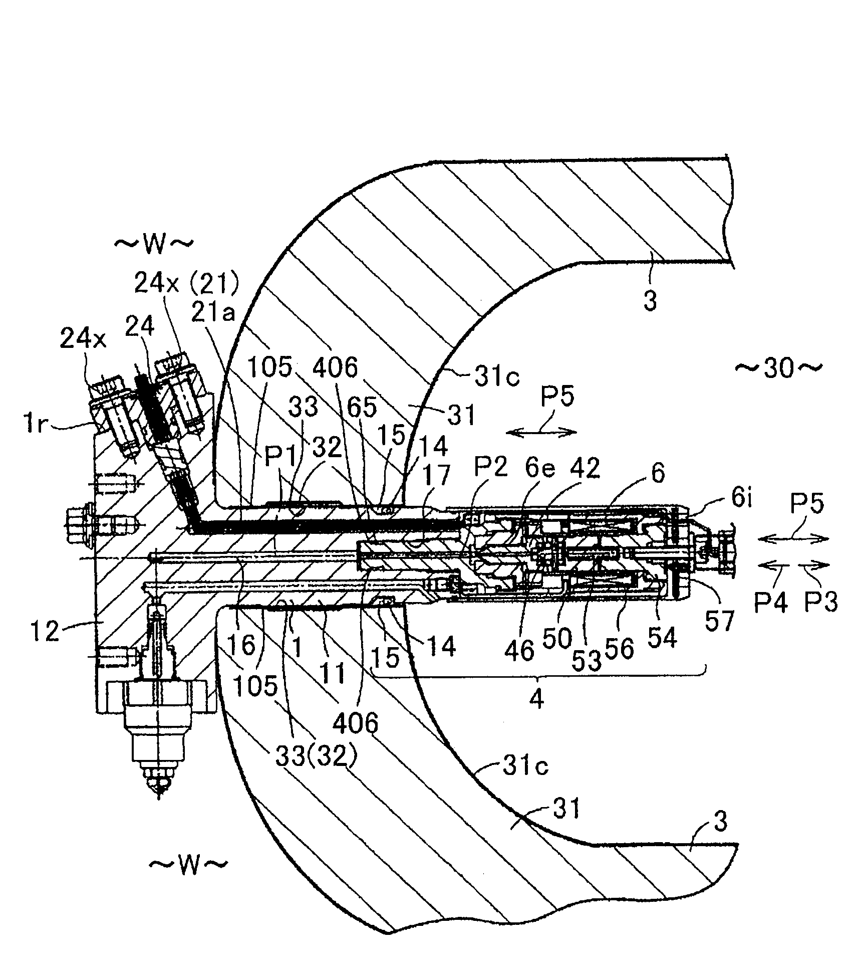
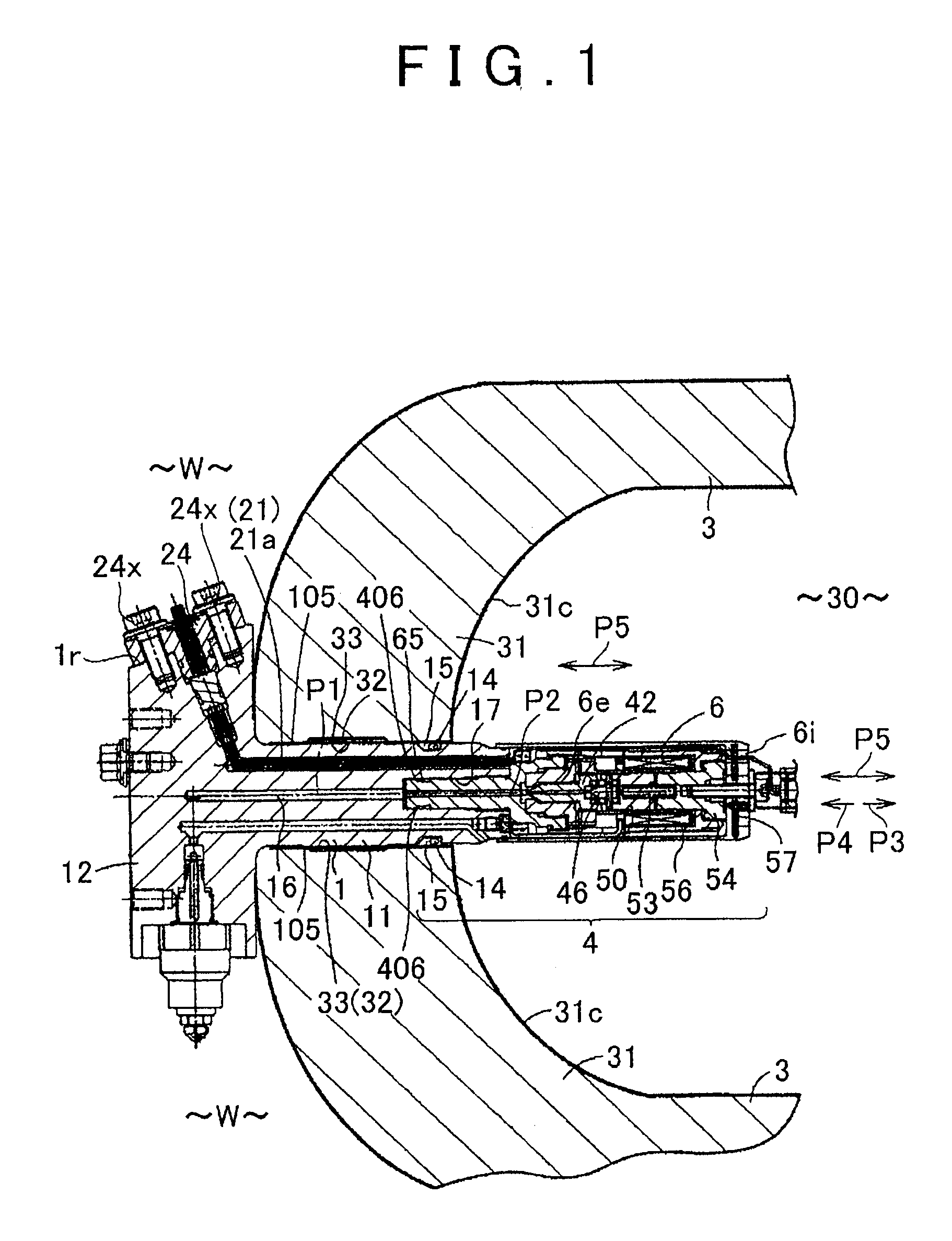
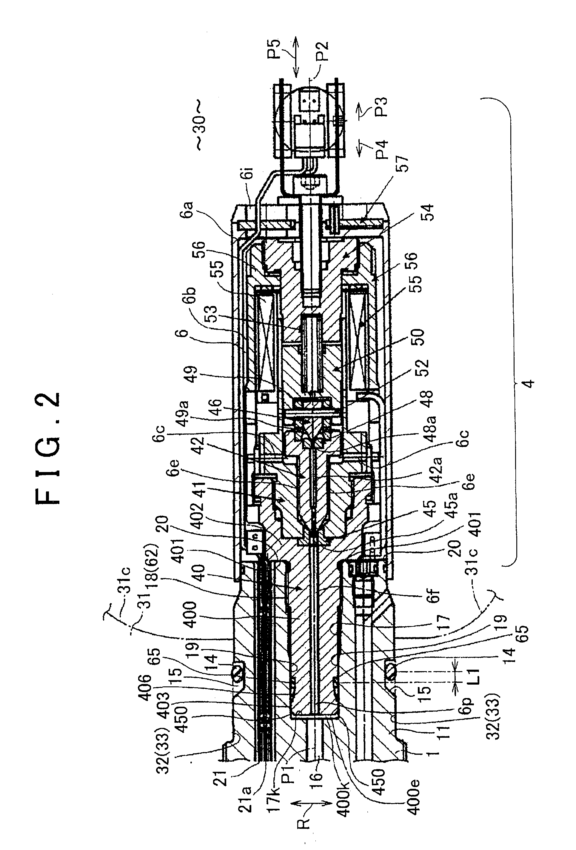
[0032]A first embodiment of the present invention will be described with reference to FIG. 1 to FIG. 6. The first embodiment is applied to a fuel cell system used in a vehicle, electrical apparatus, electronic apparatus, stationary equipment, transportable equipment, etc. Overall configuration is described first. As shown in FIG. 1 and FIG. 2, a fluid supply valve assembly device has a fixing member 1 and a fluid supply valve 4 (electrical apparatus) that is removably mounted to the fixing member 1. Overall configuration is described first.

[0033]As shown in FIG. 1, the fixing member 1 is mounted to a mounting hole 32 in a tank wall 31 with an inner surface 31c that forms a tank chamber 30 (fluid tank chamber, source of intruding gas) of a tank 3 that stores gas (hydrogen gas) at high pressure. High pressure gas (hydrogen gas) is stored in the tank chamber 30. The pressure in the tank chamber 30 is higher than atmospheric pressure and generally maintained within a range of 10 to 250 ...

second embodiment

[0064]FIG. 7 illustrates a second embodiment. This embodiment basically possesses the same configuration and effects as the first embodiment. Thus, a description is now made with its focus on the differences. As shown in FIG. 7, the other end 87f of the vent path 87 is formed in the downwardly oriented surface 24w of the plug 24. Furthermore, in order to prevent water such as rainwater existing in the outside air W from directly contacting the resistance member 9, a protective cover 95 as a protective member that protects the resistance member 9 is fixed to the plug 24 with a fastener 95x. Since the direct contact of water such as rainwater to the resistance member 9 is avoided, a longer operating life of the resistance member 9 can be achieved.

third embodiment

[0065]FIG. 8 illustrates a third embodiment. This embodiment basically possesses the same configuration and effects as the second embodiment. Thus, a description is now made with its focus on the differences. As shown in FIG. 8, in addition to the vent path 87, a second vent path 87B is formed in the fixing member 1. The second vent path 87B communicates the gas residual section 28 with the outside air W. In this way, even when one of the vent path 87 and the second vent path 87B is clogged by a foreign matter (including water), the ventilation can be performed by the other path.


PUM


Abstract

A component holding device includes: a fixing member that has a first inner wall surface that forms a first hole into which gas can be entered and a component can be inserted; a component holding section that is fit to the first hole of the fixing member and that holds the component; a sealing section that is provided in the first hole and that seals the component holding section to prevent water from entering into the first hole of the fixing member; and a vent path that is provided in at least one of the fixing member and the component holding section so as to communicate with a gas residual section in the component insertion hole and that discharges leaked gas in the gas residual section to outside air.

Description

INCORPORATION BY REFERENCE[0001]The disclosure of Japanese Patent Application No. 2008-131065 filed on May 19, 2008 including the specification, drawings and abstract is incorporated herein by reference in its entirety.BACKGROUND OF THE INVENTION[0002]1. Field of the Invention[0003]The present invention relates to a component holding device that includes a hole into which gas such as hydrogen gas is allowed to enter and in which components such as a wire and a temperature sensor are inserted and held.[0004]2. Description of the Related Art[0005]The following description is based on an example of a wire holding device that is used in a fuel cell system. A wire holding device includes: a fixing member that has an inner wall surface provided with a wire insertion hole through which a wire is inserted; and a wire holding section that holds the wire that is electrically connected to an electrical apparatus fit to the wire insertion hole of the fixing member. The wire holding device of th...

Claims


Application Information

Patent Timeline
IPC IPC(8): F16B37/04
CPCF16K31/0655H01M8/04089Y02E60/50H01M8/0662Y02E60/321H01M8/04201Y02E60/32Y10T137/5762
Inventor NUMAZAKI, KAZUSHISUZUKI, TAKUYAKUBO, TOSHIKATSU
Owner JTEKT CORP
Why Eureka
Try Eureka