
Mobile apparatus and method of timing synchronization

a mobile apparatus and timing synchronization technology, applied in the field of wireless communication, can solve the problems of accumulated timing errors exceeding timing offset tolerance, timing error generated, and computing processors

Inactive Publication Date: 2009-11-19
MEDIATEK INC
View PDF2 Cites 34 Cited by
  • Summary
  • Abstract
  • Description
  • Claims
  • Application Information

AI Technical Summary

Benefits of technology

The patent describes a method and apparatus for synchronizing the timing between a base station and a mobile station. This is achieved by measuring the number of times the mobile station clock switches from one speed to another, and comparing it to a predetermined number of switches. When the number of switches reaches the predetermined level, a control channel block is received and decoded to determine the timing error between the two clocks. The timing error is then compensated for using a clock generator. The technical effect of this invention is to improve the accuracy and reliability of timing synchronization between the base station and mobile station, which can enhance the overall performance and reliability of wireless communication systems.

Problems solved by technology

The employment of the low clock speed effectively reduce power usage for the mobile apparatus, however, there is a timing error generated every time when exiting the power saving mode as the mobile station switches from a low clock speed to a high clock speed.
When the mobile station executes an application, for example, screen saver, frequently switching between two clock speeds may cause the accumulated timing error to exceed the timing offset tolerance before receiving a next paging data block and performing timing synchronization.
The computing processor, such as a digital signal processor (DSP), is unable to performing pattern matching to detect the training sequence if the accumulated timing error exceeds the timing offset tolerance.

Method used


Image

  • Mobile apparatus and method of timing synchronization
  • Mobile apparatus and method of timing synchronization
  • Mobile apparatus and method of timing synchronization

Examples


Embodiment Construction

[0017]The following description is made for the purpose of illustrating the general principles of the invention and should not be taken in a limiting sense. The scope of the invention is best determined by reference to the appended claims.

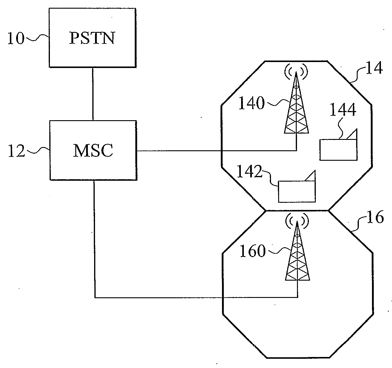
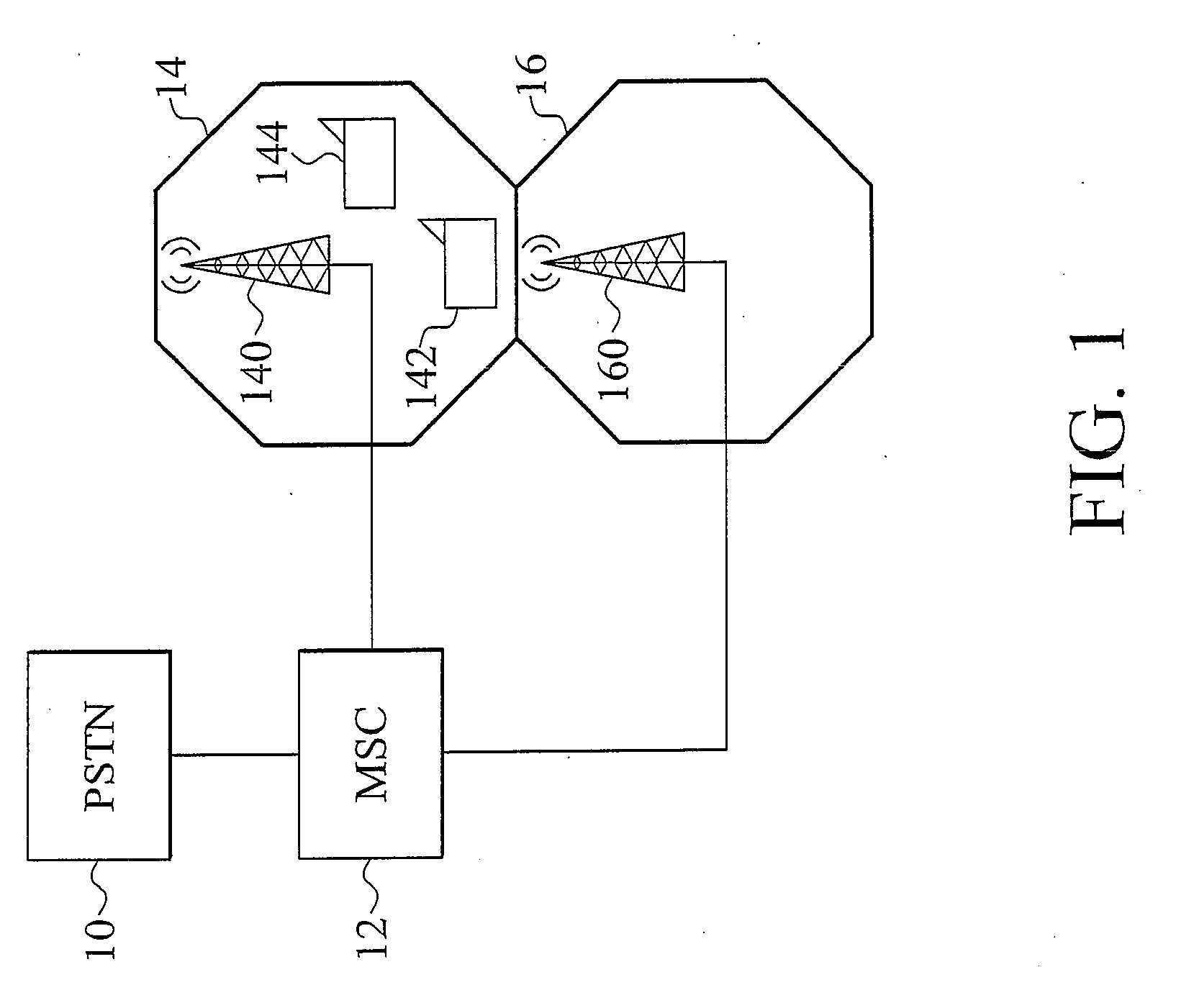
[0018]FIG. 1 is a block diagram of an exemplary wireless telecommunication system preferably incorporating embodiments of the present invention, comprising a public switching telephone network (PSTN) 10, a Mobile Service Switching Centers (MSC) 12, and base station coverage 14 and 16. The PSTN 10 is coupled to the MSC 12, and subsequently to base station coverage 14 and 16.

[0019]In the exemplary embodiment, the wireless telecommunication is a GSM system, the base station coverage 14 and 16 are provided by base stations 140 and 160 to offer telecommunication services to mobile phones 142 and 144. MSC 12 routes telephone calls that may be voice or data messages from a call source to a call destination through PSTN 10. Base stations 140 and 160 alloca...


PUM


Abstract

A mobile apparatus and method of timing synchronization. The mobile apparatus comprises a timing synchronization controller, a frame detector, a decoder, and a clock generator. The timing synchronization controller determines a number of times of the mobile station clock switching from a first clock speed to a second clock speed, and compares the number of times of the mobile station clock switching the clock speed with a predetermined number of clock speed switch. The frame detector, coupled to the timing synchronization controller, receives a control channel block when the number of times of clock speed switch reaches the predetermined number of clock speed switch. The decoder, coupled to the frame detector, decodes the control channel block to compute a timing error between the base station clock and the mobile station clock. The clock generator, coupled to the decoder, receives the timing error to compensate for the mobile station clock.

Description

BACKGROUND OF THE INVENTION[0001]1. Field of the Invention[0002]The invention relates in general to wireless communication, and in particular, to timing synchronization in wireless communication systems.[0003]2. Description of the Related Art[0004]Wireless communication systems provide voice, video, data, and signaling communication services that are widely used. For example, European Telecommunication Standard Institute (ETSI) has specified a Global Standard for Mobile Communication (GSM) that uses time division multiple access (TDMA) over radio frequency (RF) channels.[0005]The wireless communication systems cover a geographical area that is subdivided into communication cells served by at least one base station, which together provide communication coverage to a service area. The base station communicates with mobile stations over downlink and uplink RF channels to provide the wireless communication service. The RF channels are subdivided into a number of time slots or logical ch...

Claims


Application Information

Patent Timeline
Patent Type & Authority Applications(United States)
IPC IPC(8): H04B7/00
CPCH04W56/0015H04W56/00
Inventor HO, WEN HSIEN
Owner MEDIATEK INC
Learn More