
Proximity sensor device and method with swipethrough data entry

a proximity sensor and data entry technology, applied in the field of electronic systems, can solve the problems of difficult to provide a full range of input options to users with effective ease of use, limited space available on each phone for a proximity sensor device, and inability to provide flexible data entry capability in limited space, etc., to facilitate quick and easy data entry, improve user interface functionality, and facilitate the effect of improving device usability

Inactive Publication Date: 2009-11-26
SYNAPTICS INC
View PDF22 Cites 17 Cited by
  • Summary
  • Abstract
  • Description
  • Claims
  • Application Information

AI Technical Summary

Benefits of technology

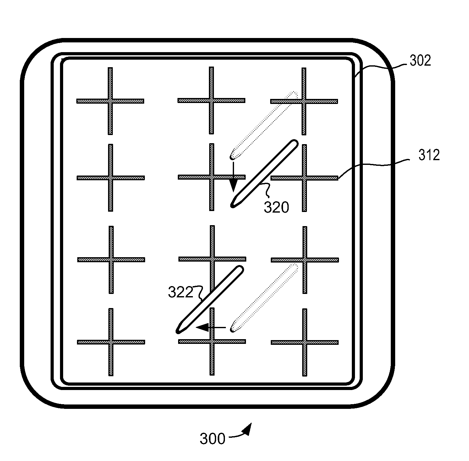
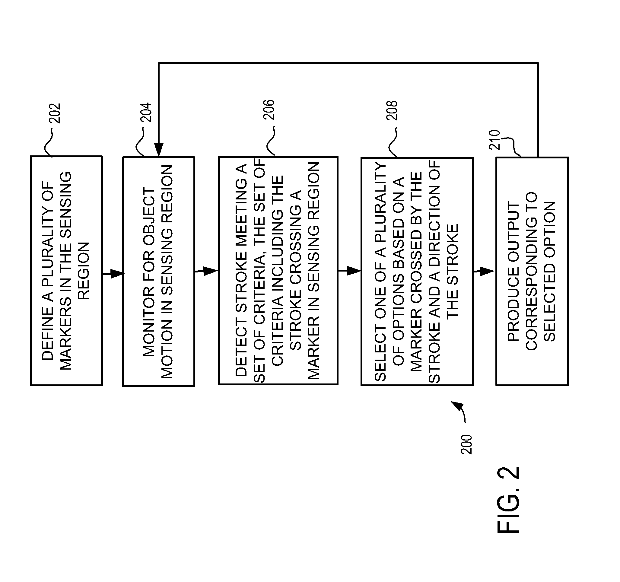
The present invention provides a device and method that improves user interface functionality by using proximity sensor devices with limited input space. The device and method allow for quick and easy data entry using markers and the direction of strokes. The processing system defines a plurality of markers and produces an output that corresponds to a selected option based on the marker crossed by the stroke and its direction. This method facilitates fast and flexible user input in a limited space.

Problems solved by technology

One issue with some past proximity sensor devices is the need to provide flexible data entry capability in limited space.
For example, on many mobile phones, the available space on each phone for a proximity sensor device is extremely limited.
In these types of sensor devices, it can be very difficult to provide a full range of input options to users with effective ease of use.
For example, relatively complex and precise gestures have been required for many types of input, thus causing data entry and other user input to be difficult and overly time consuming.

Method used


Image

  • Proximity sensor device and method with swipethrough data entry
  • Proximity sensor device and method with swipethrough data entry
  • Proximity sensor device and method with swipethrough data entry

Examples


Embodiment Construction

[0013]The following detailed description is merely exemplary in nature and is not intended to limit the invention or the application and uses of the invention. Furthermore, there is no intention to be bound by any expressed or implied theory presented in the preceding technical field, background, brief summary or the following detailed description.

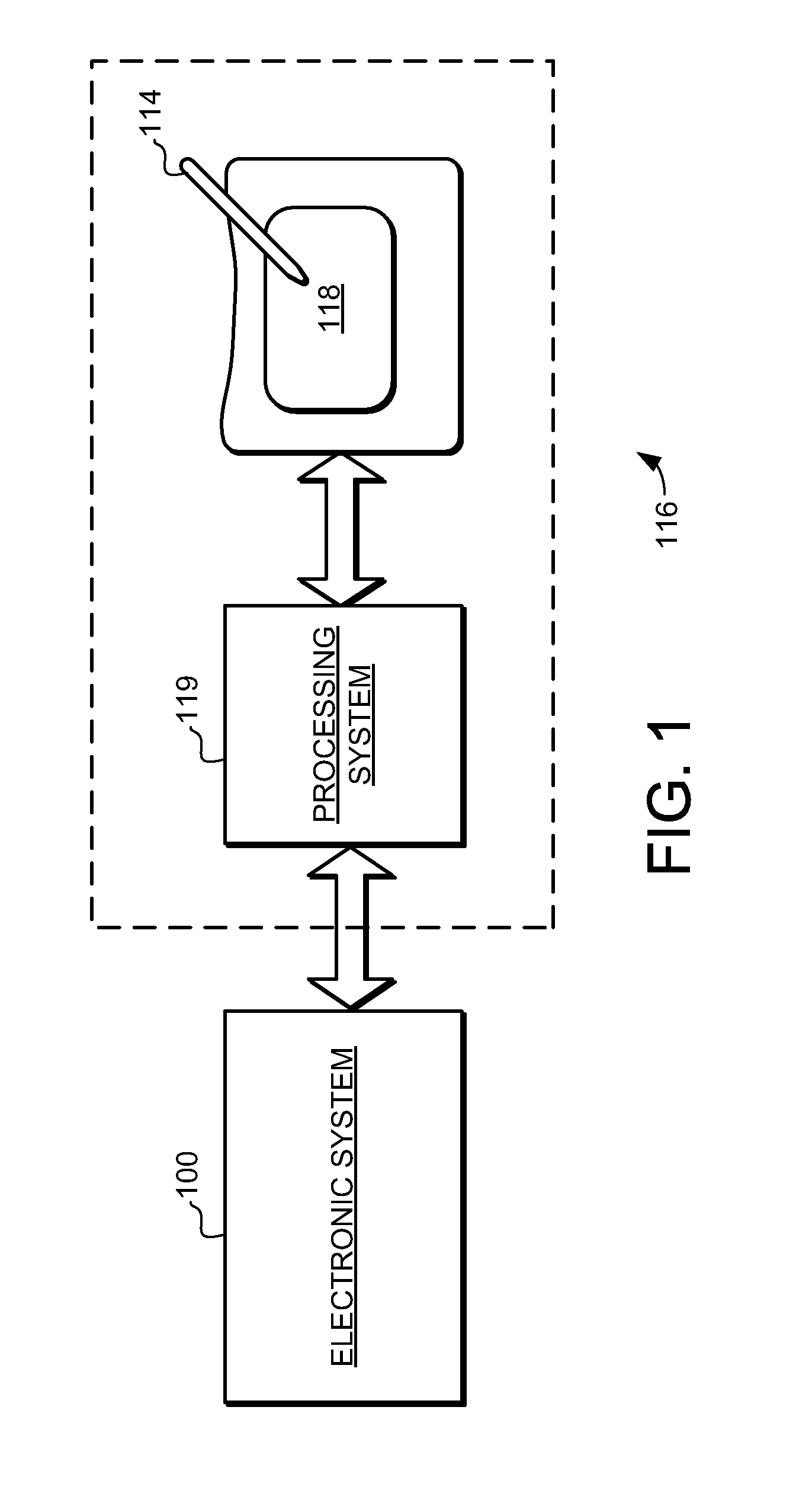
[0014]The embodiments of the present invention provide an electronic system and method that facilitates improved device usability. Specifically, the device and method provide improved user interface functionality by facilitating quick and easy data entry using proximity sensors with limited space. Turning now to the drawing figures, FIG. 1 is a block diagram of an exemplary electronic system 100 that operates with a proximity sensor device 116. As will be discussed in greater detail below, the proximity sensor device 116 can be implemented to function as an interface for the electronic system 100. Electronic system 100 is meant to represen...


PUM


Abstract

A touch sensor device and method is provided that facilitates improved device usability. Specifically, the touch screen device and method provide user interface functionality while reducing the possibility of inadvertent activation of certain functions. The touch screen device comprises a proximity sensor adapted to detect object presence in a sensing region, a display screen overlapping the sensing region, and a processing system. The touch screen device is adapted to provide user interface functionality by facilitating the display of user interface elements and the selection and activation of corresponding functions. For certain functions, the touch screen device and method uses the presence of a second object to confirm selection of a function before that function will be performed. So configured, the touch device screen is able to reduce the likelihood of inadvertent activation for certain functions on the device.

Description

FIELD OF THE INVENTION[0001]This invention generally relates to electronic system, and more specifically relates to proximity sensor devices and using a proximity sensor device for producing user interface inputs.BACKGROUND OF THE INVENTION[0002]Proximity sensor devices (also commonly called touch sensor devices) are widely used in a variety of electronic systems. A proximity sensor device typically includes a sensing region, often demarked by a surface, in which input objects can be detected. Example input objects include fingers, styli, and the like. The proximity sensor device can utilize one or more sensors based on capacitive, resistive, inductive, optical, acoustic and / or other technology. Further, the proximity sensor device may determine the presence, location and / or motion of a single input object in the sensing region, or of multiple input objects simultaneously in the sensing region.[0003]The proximity sensor device can be used to enable control of the associated electron...

Claims


Application Information

Patent Timeline
Patent Type & Authority Applications(United States)
IPC IPC(8): G06F3/041
CPCG06F3/04886G06F3/04883
Inventor CARLVIK, OLAJONSSON, LILLI ING-MARIE
Owner SYNAPTICS INC
Learn More