Lamp assemblies, lamp systems, and methods of operating lamp systems

a lamp system and lamp assembly technology, applied in the field of lamp systems, can solve the problems of reducing production efficiency, difficulty in determining how many hours the operator of the lamp system has been historically operated, and inability to determine the number of hours of operation, so as to achieve accurate tracking and be easily portable

Inactive Publication Date: 2009-11-26
BALDWIN UV
View PDF10 Cites 19 Cited by
  • Summary
  • Abstract
  • Description
  • Claims
  • Application Information

AI Technical Summary

Benefits of technology

[0013]In an alternate embodiment in which the lamp system further includes a data writer, the data on the data carrier represents a number of hours of operation associated with the lamp assembly. The data reader is used to read the data representing the hours of operation from the data carrier when the lamp assembly is installed in the lamp system. The controller then tracks the time over which the lamp assembly is operated by the lamp system and stores the cumulative operating time. The data writer is configured to write data representing the cumulative number of hours of operation back to the data carrier, which stores the data for future use. When the lamp assembly is used in different lamp systems, the data representing the number of hours of operation is carried by the data carrier along with the lamp assembly and is readily accessible to any arbitrary lamp system to which the lamp assembly is coupled. As a result, the lamp assembly is readily portable among different lamp systems with the operational life of the lamp assembly being accurately tracked by the information stored on the data carrier.

Problems solved by technology

An operator of the lamp system currently lacks any way of determining how many hours the lamp assembly has been historically operated.
These exchanges compound the operator's difficulty in determining how many hours that any particular ultraviolet lamp assembly has been operated.
If, during the drying or curing process, the lamp assembly fails or the ultraviolet output drops to an insufficient level, the process must be interrupted to replace the lamp assembly.
Because the entire drying or curing process must be halted to install the new lamp assembly, such interruptions reduce production efficiency.
Because lamp assemblies are moved between different lamp systems with increasing frequency, this further compounds the problems of the operator in having a precise knowledge of the number of hours that a specific ultraviolet lamp assembly has been operated.
In contemporary lamp systems, the configuration of the lamp head to operate properly with specific types of lamp assemblies and the tracking of the end of life for a lamp assembly are performed manually, which is prone to errors.
For instance, if the operator neglects the recording of the manual tracking, operation of the lamp system may be interrupted because there is no way to anticipate that a particular lamp assembly is nearing its end of life.

Method used


Image

  • Lamp assemblies, lamp systems, and methods of operating lamp systems
  • Lamp assemblies, lamp systems, and methods of operating lamp systems
  • Lamp assemblies, lamp systems, and methods of operating lamp systems

Examples


Embodiment Construction

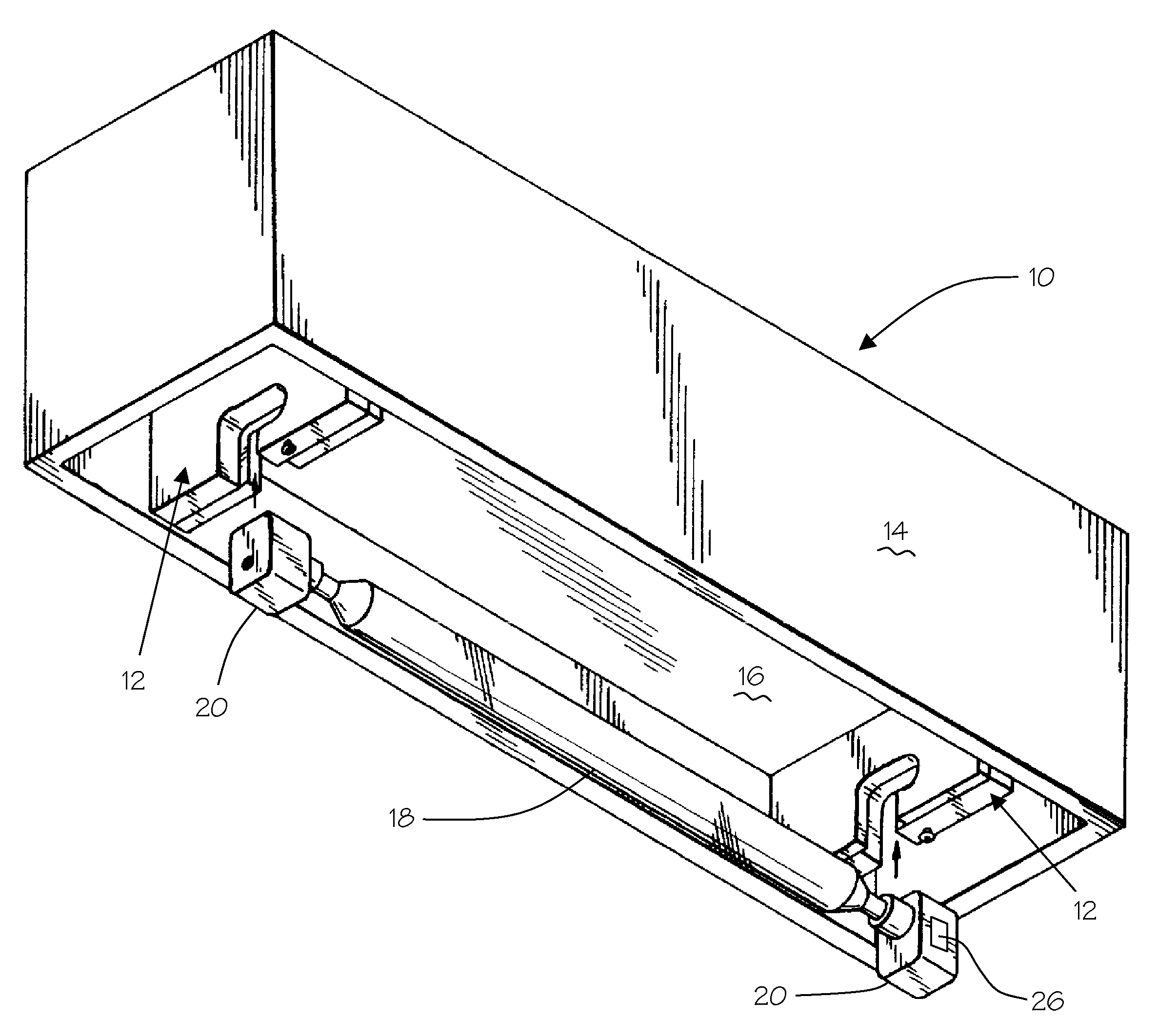
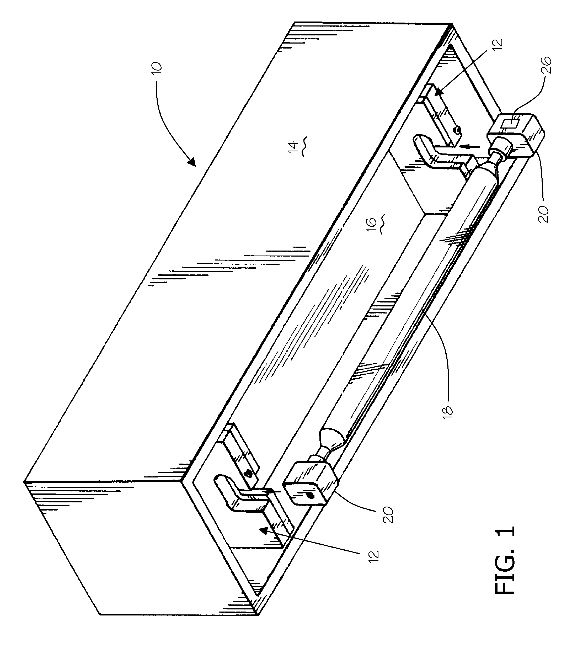
[0024]Turning to the drawings, wherein like numbers denote like parts throughout the several views, FIGS. 1 and 2 show an exemplary lamp head 10 that incorporates a lamp-retaining device 12. The lamp head 10 also includes a lamp housing 14 which may be operatively connected to a source of cooling water and a source of electricity (diagramatically shown in FIG. 3). In some configurations, the lamp housing 14 may include a water cooled section 16 which is operatively connected to the source of cooling water. The water cooled section 16 serves to cool the lamp head 10 while it is operational, such as during a curing application. The lamp system further includes a lamp assembly 24 which is selectively removable from the lamp retaining device 12 in the lamp head 10. The lamp head 10 may include a reflector (not shown), which includes a reflective surface partially surrounding the lamp 18 for reflecting radiation onto a substrate.

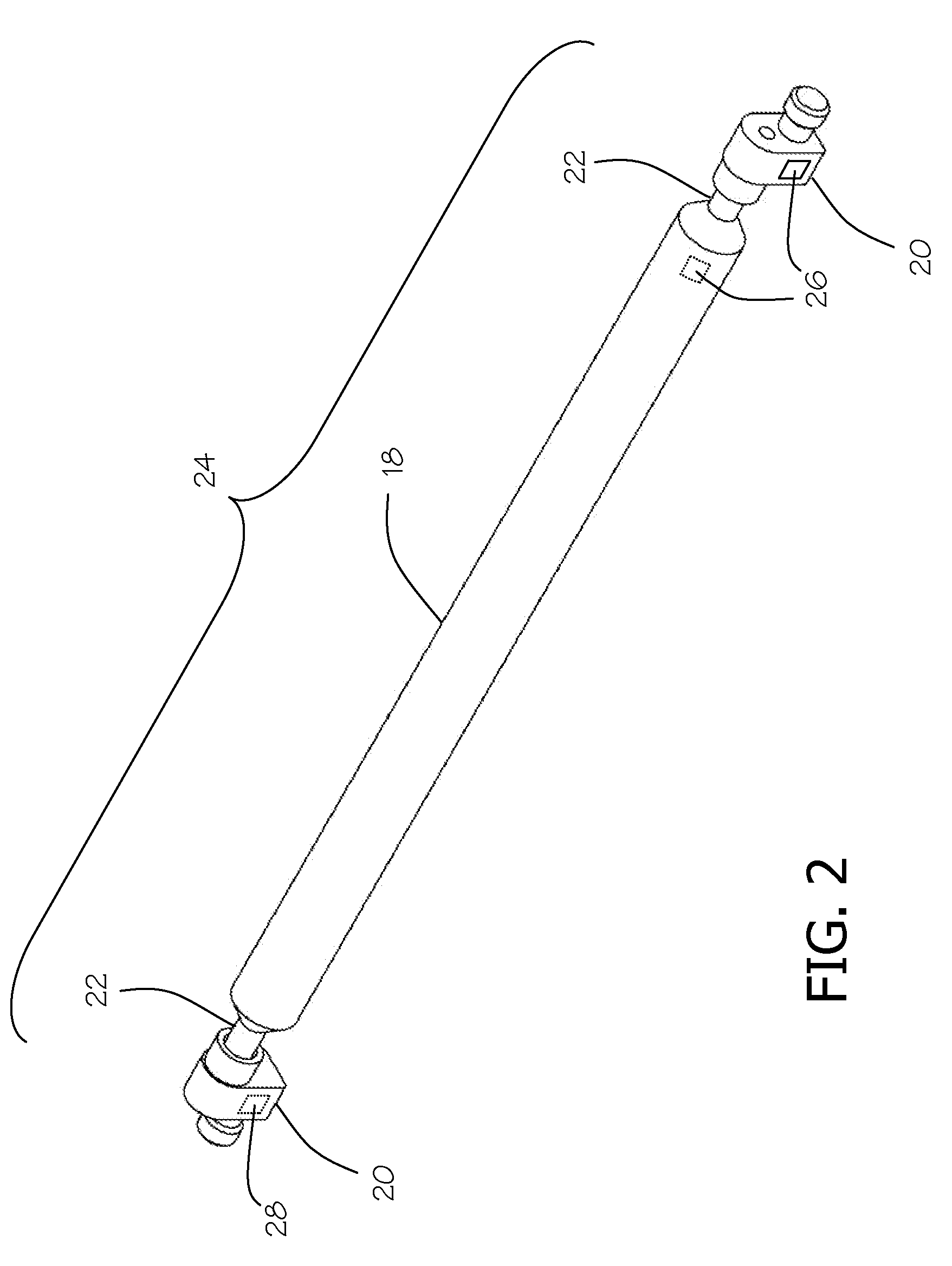
[0025]The lamp assembly 24 includes lamp 18 and end fixture...


PUM


Abstract

Lamp systems, lamp assemblies, and methods of operating a lamp system are provided. The lamp system includes a lamp head and a lamp assembly having at least one end fixture for securing the lamp assembly in the lamp head. A data carrier is mounted to lamp assembly. The data carrier is configured to store an identifier, or operational data, or data representing the number of hours of operation, or data representing the lamp type associated with the lamp assembly, or any combination thereof. A data reader is configured to read information stored on the data carrier. A controller is operable to process the information read from the data carrier. The data carrier may alternatively store data representing the number of hours of operation and the lamp system may further include a data writer for updating the stored data to reflect operation of the lamp assembly.

Description

TECHNICAL FIELD[0001]This invention relates generally to lamp assemblies, lamp systems, and methods of operating such lamp systems for use in curing or drying adhesives, sealants, inks, coatings, and other types of materials.TECHNICAL BACKGROUND[0002]Lamp systems are commonly used for curing or drying adhesives, sealants, inks, coatings, and other similar materials. A conventional ultraviolet lamp system typically includes an lamp assembly and a lamp head to which the lamp assembly is mounted. The lamp assembly includes an bulb or lamp defining an envelope that confines a spectral fill (mercury, gallium, iron, etc.) and a pair of holders secured to the opposite ends of the lamp. In certain varieties of lamp systems, each of the holders is connected to a power source via the lamp head for energizing the spectrial fill confined inside the lamp. When energized, the gases of the spectral fill emit radiation in the ultraviolet band of the electromagnetic spectrum.[0003]As can be apprecia...

Claims


Application Information

Patent Timeline
Patent Type & Authority Applications(United States)
IPC IPC(8): H05B37/02G04B47/00
CPCH05B41/36F21V23/00H05B47/20
Inventor ARMITAGE, DAVIDDRAYTON, JONATHANSTOWELL, QUINTON
Owner BALDWIN UV
Why Eureka
Try Eureka