
Secure electromagnetic data storage element having a plurality of selectively determined switchable security modes

Inactive Publication Date: 2009-11-26
ZHENUINE CORP
View PDF20 Cites 15 Cited by
  • Summary
  • Abstract
  • Description
  • Claims
  • Application Information

AI Technical Summary

Benefits of technology

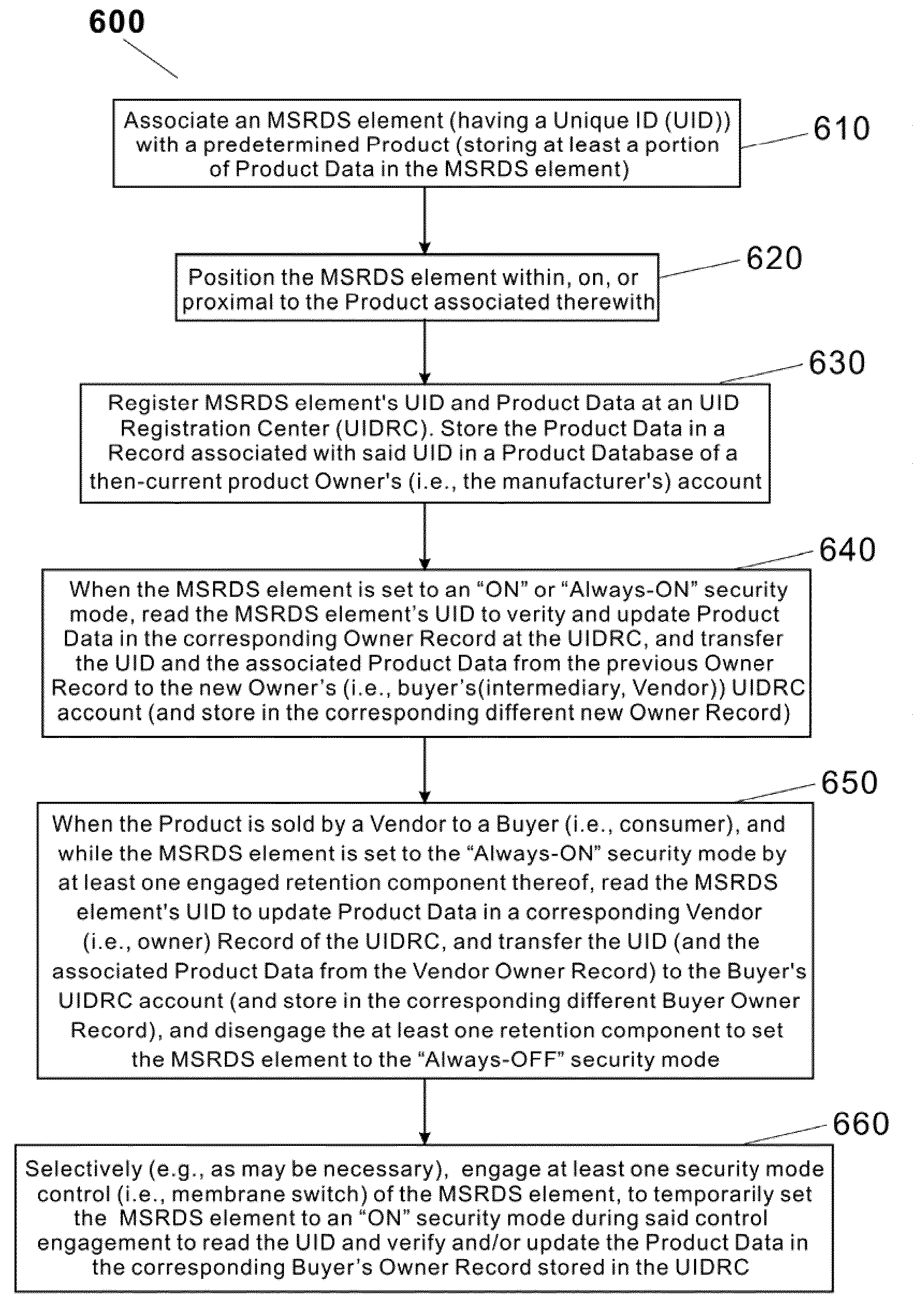
[0056](5) one or more releasable retention components, corresponding to one or more of the membrane switches, to readily enable selective switching back and forth between “Always-ON” and “Always-OFF” security modes through selective retention of one or more membrane switches of a RDS device in an activated position (and / or selective release of at least one membrane switch therefrom).
[0063]Therefore, the MSRDS element of the present invention provides a greater level of data security than previously known solutions, but is also advantageously balanced with convenience—the inventive MSRDS element is freely accessible prior to acquisition of the product associated therewith by a user, and is thereafter easily made secure by the user, who is provided with the capability of readily and selectively enabling access to the data stored therein by operating the MSRDS element's security mode control. Optionally, the pressure layer retention component may be re-insertable by the user, such that if the user desires to return the MSRDS element to an Always-ON security mode, they may do so by returning the pressure layer retention component to its previous position within the MSRDS element in which it exerts continual pressure on the membrane switch.
[0066]The layer-based construction of the novel MSRDS element, and its membrane-based security mode control embodiments, enable easy and inexpensive fabrication of the MSRDS element, makes it readily accessible to, and operable by, the user, and further increases the MSRDS element reliability by providing at least one security mode control thereto, that does not damage the MSRDS element in which it is implemented, even after repeated utilization. One or more optional EM / EMI shielding layer may also be provided for protecting the electronic component(s) of the MSRDS element from undesirable electromagnetic influence, and to prevent various contact pads in the MSRDS element from acting as antennae susceptible to unauthorized interrogation.

Problems solved by technology

However, conventional RDS devices suffer from a serious disadvantage-specifically, an unauthorized party (with a compatible RDS device reader or equivalent) who is within a predefined interrogation range of a typical RDS device may be able to access, delete, and possibly even alter the data stored in the device.
Clearly, this disadvantage becomes a critical issue in certain RDS applications, such as security and / or e-commerce, in which individuals' personal and / or financial information may be stored in the RDS device, and thus be subject to access and / or misappropriation by unauthorized third parties.
However, such a crude “solution” does not in any way address the numerous applications in which further use of the RDS device is necessary after the event, nor does it address the applications in which it may be desirable to keep a RDS device in an inactive mode until after a particular predetermined event occurs.
However, each of those solutions suffers from one or more serious disadvantages, and none of the previously known solutions adequately address the full extent of the abovementioned challenges.
No. 2007 / 0290051, entitled “Contactless Card With Membrane Switch Made of Elasto-Resistive Material”, both references propose RDS devices that are based on complex on / off RFID / contactless card switches that utilize mechanical parts and / or that incorporate special contact-based materials in their construction, and that are, as a result, more difficult to fabricate.
The complexities in their construction and implementation, also render such switches overly sensitive to disturbances to the RDS device in which they are incorporated.
However, these RDS device may still be subjected to unauthorized interrogation (albeit at a shorter range), and are difficult, if not impossible to re-use.
Also none of Mr. Colby's patents show or describe any way to permanently change the default mode of operation of the RFID tag from being always active to being always off.
For example, during multiple key stages of their production and distribution, products supplied with the above-described RFID tag would be of no use—they are fabricated, stored, and then transported from a manufacturer to a retailer, all without being able to the RFID tag to for tracking / management purposes tracking until conductive material is removed from the tag, revealing its antenna, and thus undesirably bringing all of the above-described access vulnerabilities and security flaws into play.

Method used


Image

  • Secure electromagnetic data storage element having a plurality of selectively determined switchable security modes
  • Secure electromagnetic data storage element having a plurality of selectively determined switchable security modes
  • Secure electromagnetic data storage element having a plurality of selectively determined switchable security modes

Examples


Embodiment Construction

[0070]The apparatus of the present invention are directed to a selectively accessible electromagnetically resonant data storage element (that may be implemented as a resonant tag, card, and / or embedded element integrated into a product), that is selectively responsive to predetermined electromagnetic interrogation thereof, that comprises a novel membrane switch component for enabling a user to selectively enable and / or disable interrogatory access to the resonant component, to protect from unauthorized interrogation thereof (hereinafter “MSRDS element”).

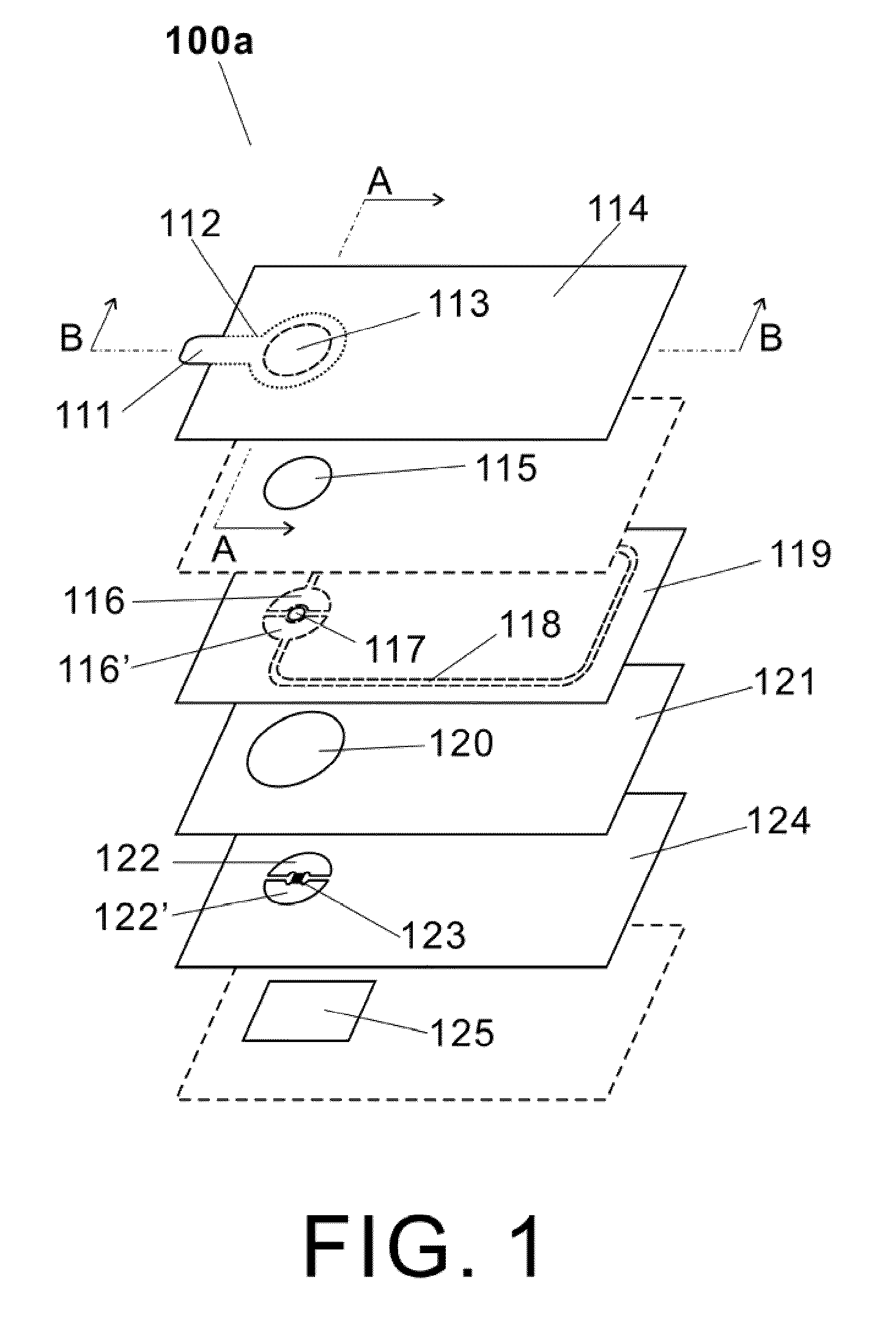
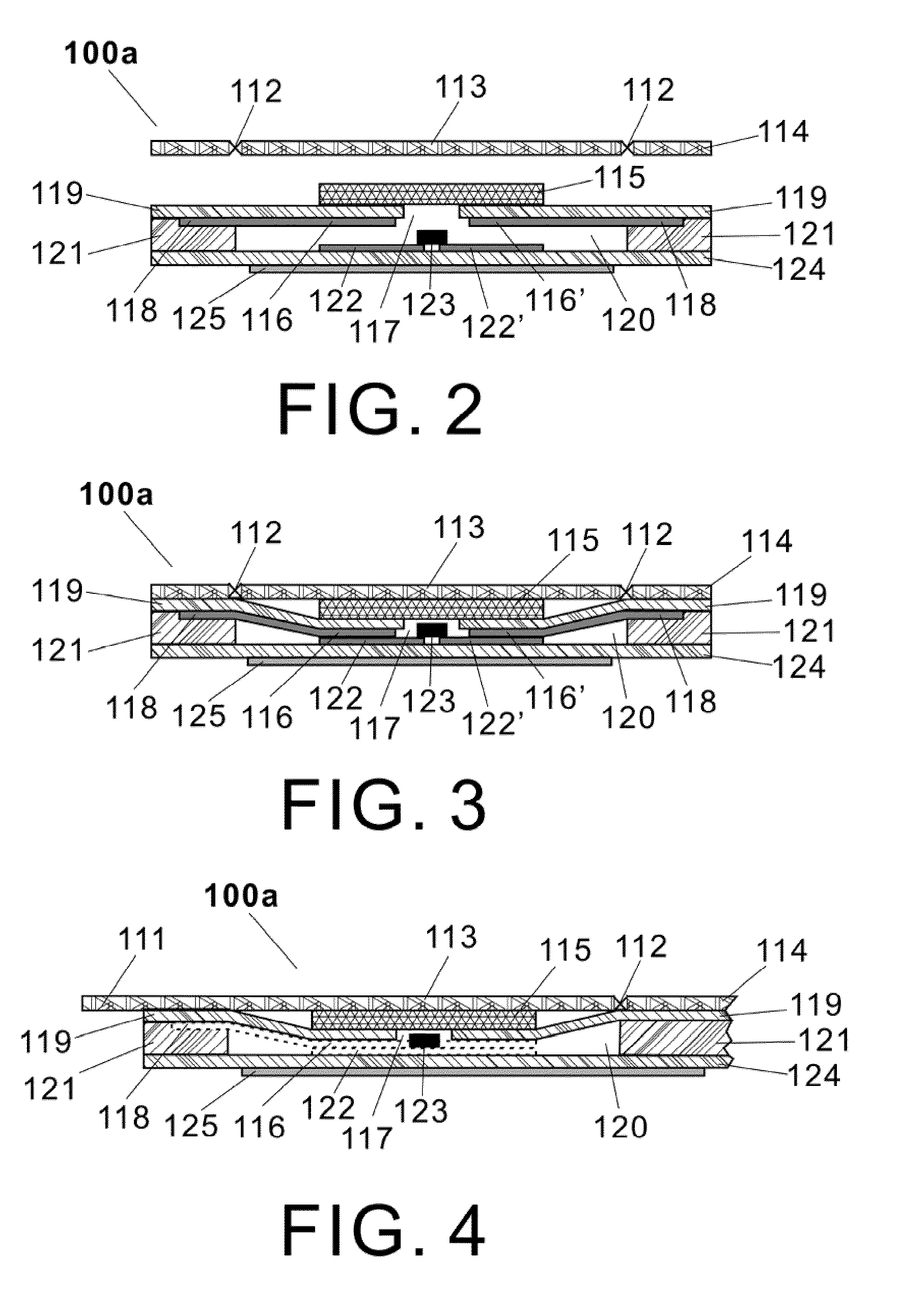
[0071]In summary, the inventive MSRDS element comprises a top circuitry layer, a bottom circuitry layer, which includes a microchip, a plurality of contact pads and an antenna, an insulation spacer layer, a pressure layer retention component, and an optional EM / EMI shielding layer. The membrane switch may be formed through a combination of aligned and configured subcomponents of at least a portion of the element's layers. In one embo...


PUM


Abstract

The apparatus of the present invention are directed to an selectively accessible electromagnetically resonant data storage element (implemented as a resonant tag, card, and / or embedded element), that is selectively responsive to predetermined electromagnetic interrogation thereof, that comprises a novel membrane switch component for enabling a user to selectively enable and / or disable interrogatory access to the resonant component, to protect from unauthorized interrogation thereof (hereinafter “MSRDS element”). The inventive MSRDS element comprises a top circuitry layer, a bottom circuitry layer, which includes a microchip, a plurality of contact pads and an antenna, an insulation spacer layer, a pressure layer retention component, and an optional EM / EMI shielding layer. The membrane switch may be formed through a combination of aligned and configured subcomponents of at least a portion of the element's layers. In one embodiment thereof, the pressure layer retention component may be advantageously utilized to maintain the membrane switch in a pressed down position to thereby enable the MSRDS element to function continuously (i.e., in an Always-ON security mode), until such time that the pressure layer retention component is removed. In this exemplary embodiment of the MSRDS element, for example used in conjunction with consumer products, when a consumer purchases a product that has been provided with the MSRDS element, they remove (e.g., peel off, etc.) the pressure layer retention component to change the element to an Always-OFF security mode, such that the MSRDS element is only accessible to electromagnetic interrogation thereof when the membrane switch is held down. Therefore, the MSRDS element of the present invention provides a greater level of data security advantageously balanced with convenience—it is freely accessible prior to acquisition thereof by a user, and is thereafter easily made secure by the user, who is provided with the capability of readily and selectively enabling access to the data stored therein.

Description

CROSS-REFERENCE TO RELATED APPLICATIONS[0001]The present patent application is a continuation-in-part of, and claims priority from, the U.S. patent application of Yu Yung Choi, entitled “SECURE ELECTROMAGNETIC DATA STORAGE ELEMENT HAVING A PLURALITY OF SELECTIVELY DETERMINED SWITCHEABLE SECURITY MODES” (Ser. No. 12 / 481,490), filed on Jun. 9, 2009, which in turn claims priority from U.S. Provisional Patent Application of Yu Yung Choi, entitled “MEMBRANE SWITCH FOR ENABLING AND DISABLING THE RESONANT TAG AND / OR CARD” (Ser. No. 61 / 059,809), filed on Jun. 9, 2008, and which also claims priority from U.S. Provisional Patent Application of Yu Yung Choi, entitled “MEMBRANE SWITCH FOR ENABLING AND DISABLING THE RESONANT TAG AND / OR CARD” (Ser. No. 61 / 082,243), filed on Jul. 21, 2008. The present patent application is also a continuation-in-part of, and claims priority from, the U.S. patent application of Yu Yung Choi, entitled “SYSTEM AND METHOD FOR STREAMLINED REGISTRATION OF ELECTRONIC PRO...

Claims


Application Information

Patent Timeline
IPC IPC(8): H04Q5/22G06K19/06
CPCG06K19/07345
Inventor CHOI, YU YUNG
Owner ZHENUINE CORP
Learn More