Laser cladding of tubes

a technology of laser and tube, which is applied in the field of laser cladding of tubes, can solve the problems of not being able to coordinate with the activity provided by the laser end, difficulty in vertical introduction of powder, and known devices welding on constantly changing surfaces, etc., and achieves the effect of reducing dust and back spatter

a technology of laser and tube, which is applied in the field of laser cladding of tubes, can solve the problems of not being able to coordinate with the activity provided by the laser end, difficulty in vertical introduction of powder, and known devices welding on constantly changing surfaces, etc., and achieves the effect of reducing dust and back spatter

US20090291197A1Inactive Publication Date: 2009-11-26FRAUNHOFER USA

Image

  • Laser cladding of tubes
  • Laser cladding of tubes
  • Laser cladding of tubes

Examples


example

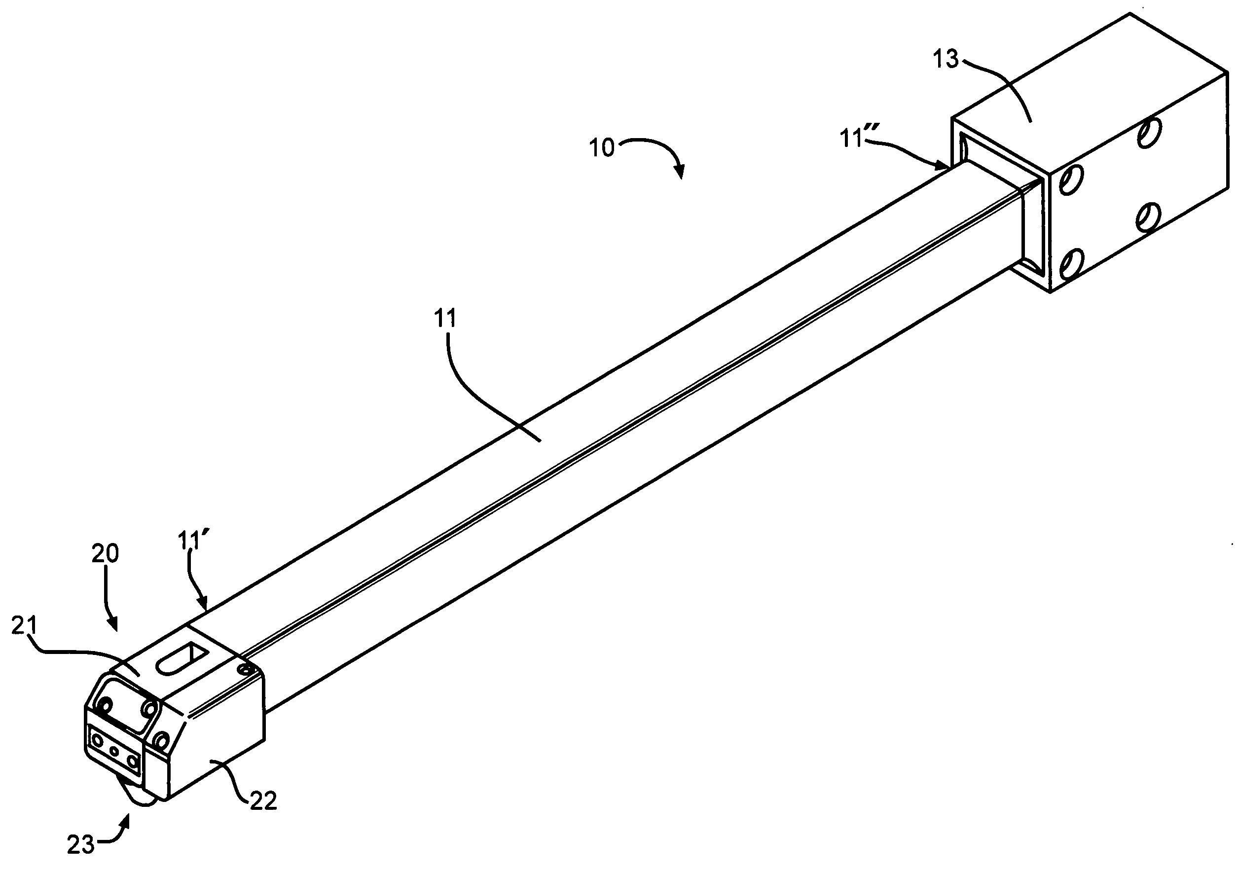
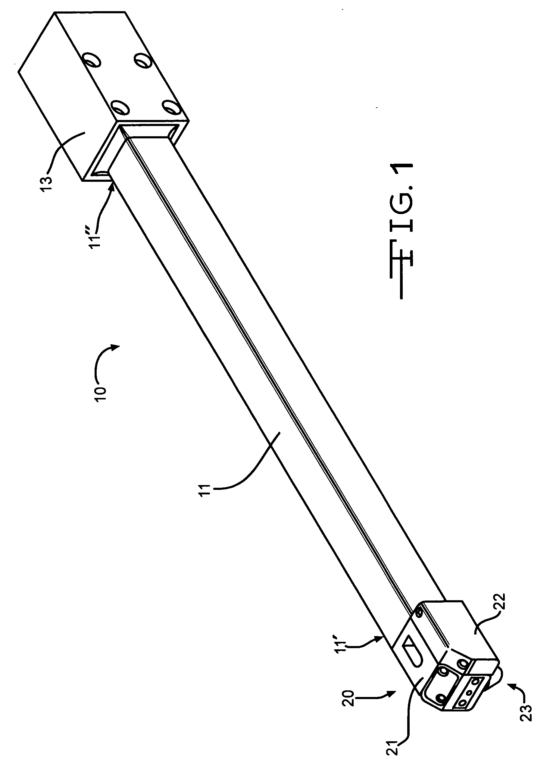
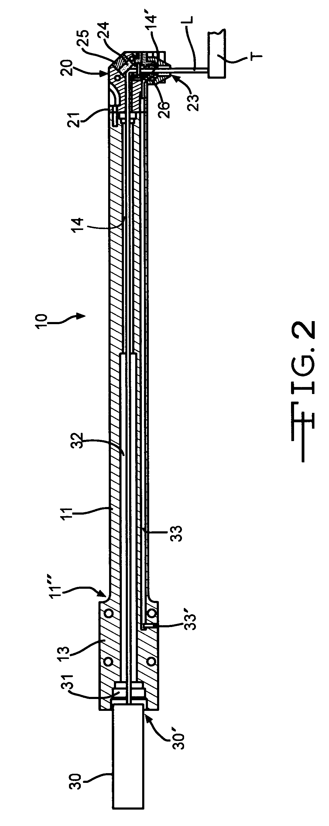
[0052]In an exemplary embodiment as shown in FIG. 10, apparatus 10 can be attached to either a robot arm or any Computer Numerical Control (CNC) machine represented schematically by box 100. Tube 90 is held in a chuck (not shown). The robot / CNC 100 is programmed to allow the cladding head 20 to travel inside the tube to the required spot X. Robot / CNC 100 is programmed to switch on the powder feeder for 15 seconds prior to laser start. This time lag allows the powder to reach a stable feed rate. The program turns ON the laser while simultaneously turning tube 90 (i.e., rotating the tube continuously). Tube 90 turns 180° while apparatus 10 remains at the same position. Apparatus 10 is then moved out of the tube along tube 90's longitudinal axis while tube 90 rotates. This creates a spiral cladding motion. The linear motion of apparatus 10 and the rotation of tube 90 are programmed so that the pitch remains constant. For example: To obtain 2 mm pitch, the head has to move linearly by 2...


PUM

PropertyMeasurementUnit
operating temperatureaaaaaaaaaa
thicknessaaaaaaaaaa

Abstract

The present invention relates to an apparatus for laser cladding of a curved surface comprising: (a) an elongated arm having first and second ends and defining a chamber through the arm from the first end to the second end; (b) a laser delivery source connected to a focusing lens mounted in a housing within an opening on the first end of the arm for delivering a laser beam through the chamber; (c) a delivery head mounted on the second end of the arm comprised of (i) an enclosure having an inlet for receiving the laser and an outlet for delivering the laser to the curved surface, (ii) a powder nozzle for delivering a cladding powder to an inner surface of the curved surface, and (iii) a reflective surface for reflecting the laser to exit through the outlet; (d) mounting means for rotating the curved surface for the cladding of the curved surface; and (e) indexing means for moving the arm substantially parallel to a longitudinal axis of the curved surface so as to clad the curved surface during the rotation of the curved surface. Typically, the curved surface is part of the inner surface of a tube used in industrial applications.

Description

CROSS-REFERENCE TO RELATED APPLICATIONS[0001]Not Applicable.STATEMENT REGARDING FEDERALLY SPONSORED RESEARCH OR DEVELOPMENT[0002]Not Applicable.REFERENCE TO A “COMPUTER LISTING APPENDIX SUBMITTED ON A COMPACT DISC”[0003]Not Applicable.BACKGROUND OF THE INVENTION[0004](1) Field of the Invention[0005]The present invention relates generally to an apparatus and a process for laser coding of the inner diameter of tubes.[0006](2) Description of the Related Art[0007]Industrial coating or cladding of tubes is well known. In the oil and drilling industry, tubes of various sizes often demand inner diameter coating, welding or cladding with a desired material. Lasers have been utilized as a coating process by melting the coating material with the desired surface to generate a “melt pool” which subsequently hardens.[0008]Laser welding of the inner diameter (ID) of barrels involves the depositing of a liner material prior to welding in the form of paste or powder, or a separate liner tube. In th...

Claims


Application Information

Patent Timeline
26 Nov 2009
Publication
US20090291197A1
IPC
C23C14/14; C23C14/54
CPC
B23K26/02; B23K26/0823; B23K26/0869; B23K26/1411; B23K26/345; B23K26/34; B23K2201/06; C23C24/10
Inventors
BARTELS, FLORIAN; JONNALAGADDA, ARAVIND