Automated detection of asymptomatic carotid stenosis
Inactive Publication Date: 2009-11-26
THE BOARD OF TRUSTEES OF THE LELAND STANFORD JUNIOR UNIV
11 Cites 18 Cited by
AI-Extracted Technical Summary
Problems solved by technology
Measuring the peak velocities can be difficult because the measured velocities are functions of an angle, referred to as the Doppler angle, between the flow direction and the transducer axis of the ultrasound used to make the measurement.
Inaccurate estimates of Doppler angle ΘD can lead to inaccurate readings of the PBV, and thus, limit efficient detection of those a...
Method used
[0033]In a preferred embodiment, the transducer array 610 is divided into a number of transducer sub-arrays 611-615. Each of the sub-arrays measures one of the ultrasound images. In other words, the transducer array is divided so that each sub-array is dedicated to measure a single planar cross-section of the blood vessel. By dividing the transducer array 610, the electronics 620 can be simplified. In an embodiment, the transducer array 610 includes multiple acoustic lenses 640, wherein each of the acoustic lenses 640 corresponds with one of the sub-arrays 611-615. An acoustic lens 640 determines the transect angle of the planar cross-section imaged by its corresponding sub-array. As described above, a transect angle less than about 45 degrees is preferred. In an embodiment, the transducer array 610 includes asymmetric acoustic lenses to set the transect angle.
[0034]The ultrasound transducer of the present invention can have any o...
Benefits of technology
[0010]The present invention is directed to a method for determining peak velocity of fluid flowing in a blood vessel. The method includes measuring a set of spatially proximate ultrasound images along the blood vessel, wherein the set of ultrasound images are measured with an ultrasound transducer, wherein each of the ultrasound images is of a planar cross-section, oriented along the ultrasound beam, of the blood vessel, and wherein each of the ultrasound images provides a time-varying Doppler-generated velocity map of the component of the fluid...
Abstract
Peak blood velocity measurement for automated stenosis detection is provided. Ultrasound measurements of the peak blood velocity are corrected by a calculation of the Doppler angle, which exists from misalignment of the ultrasound transducer axis and the true blood velocity. The direction of the blood velocity and the Doppler angle are found by imaging a set of planar cross-sections of a blood vessel, such as the carotid artery, to obtain velocity maps of the blood flowing in the blood vessel. Peak blood velocity can be correlated with an amount of stenosis therefore accurate peak blood velocity measurements are necessary for medical diagnosis. Automated stenosis detection allows for implementation in many medical settings. A capacitive micromachined ultrasound transducer array is also provided to measure the planar cross-sectional images.
Application Domain
Blood flow measurement devicesInfrasonic diagnostics +3
Technology Topic
Carotid imtMeasurement plane +16
Image
Examples
- Experimental program(1)
Example
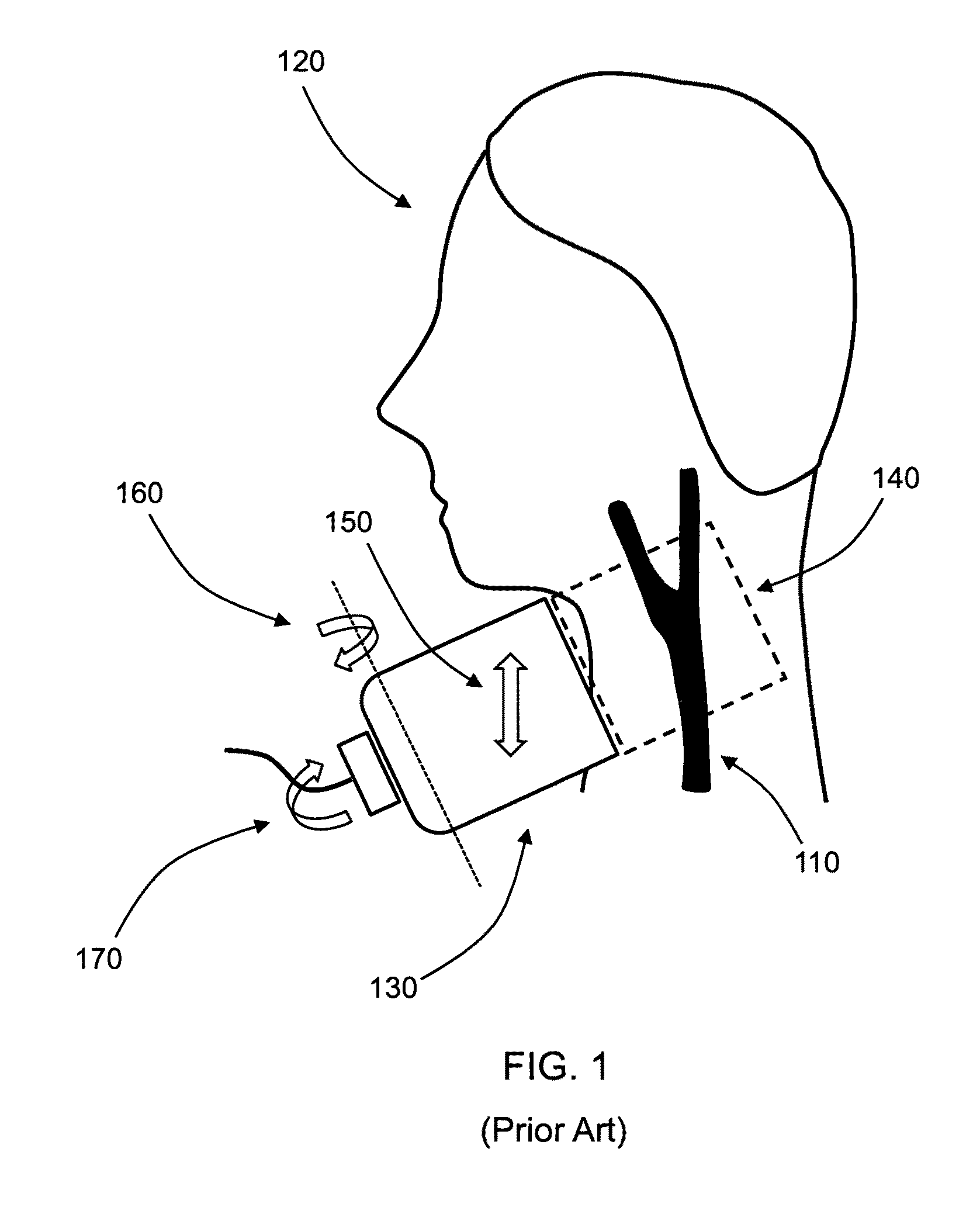
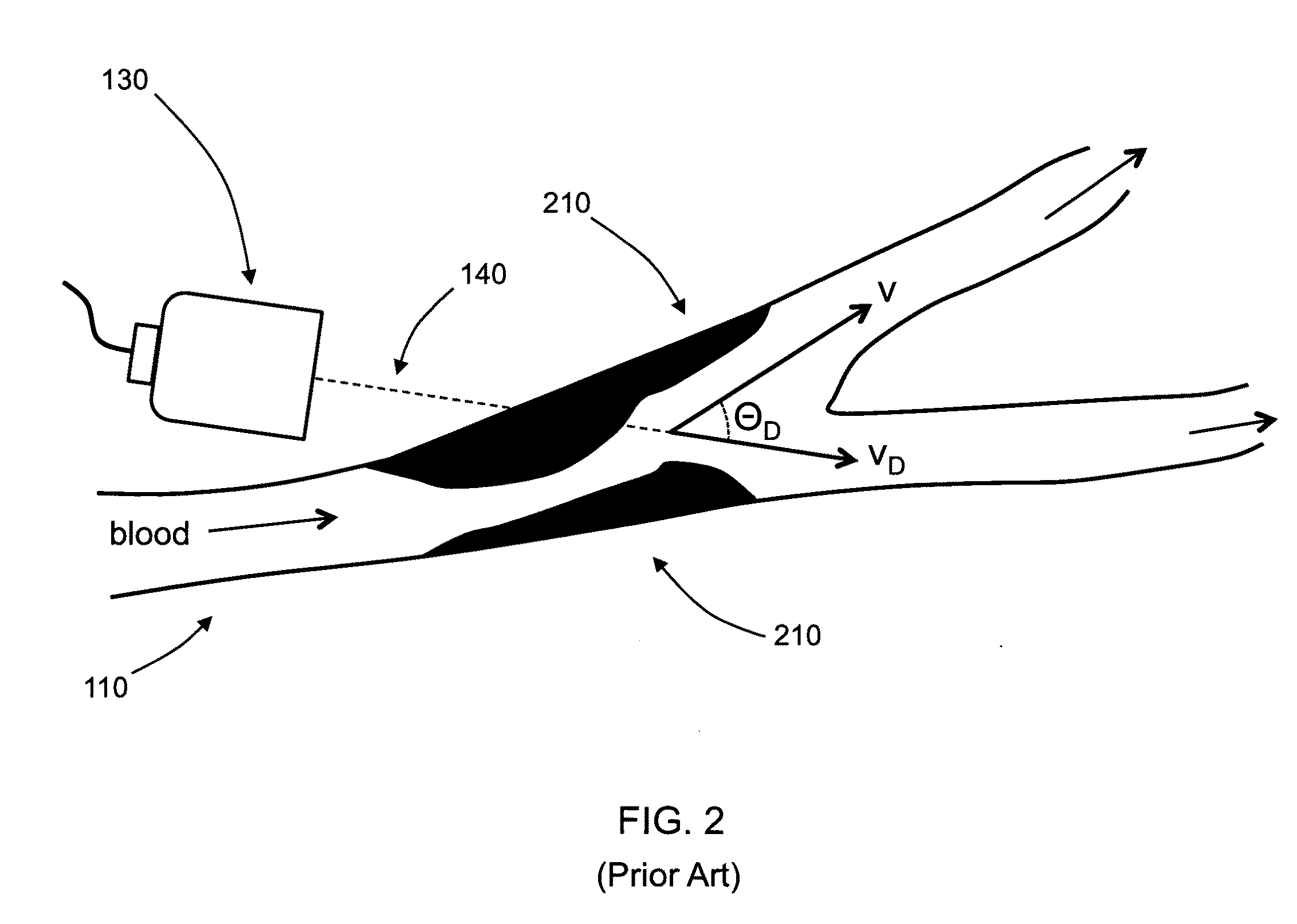
[0023]The common occurrence of stroke, particularly due to asymptomatic carotid stenosis, indicates that detection of stenosis is an important and vital medical procedure. Unfortunately, accurate stenosis detection can be a daunting task. Though affordable ultrasound techniques have been developed, existing devices can only measure velocity longitudinal to the axis of the device, thereby causing ambiguous measurements of the peak blood velocity (PBV). Often, a skilled expert is required to accurately operate the device for true PBV measurement and determination of patients at risk for stroke.
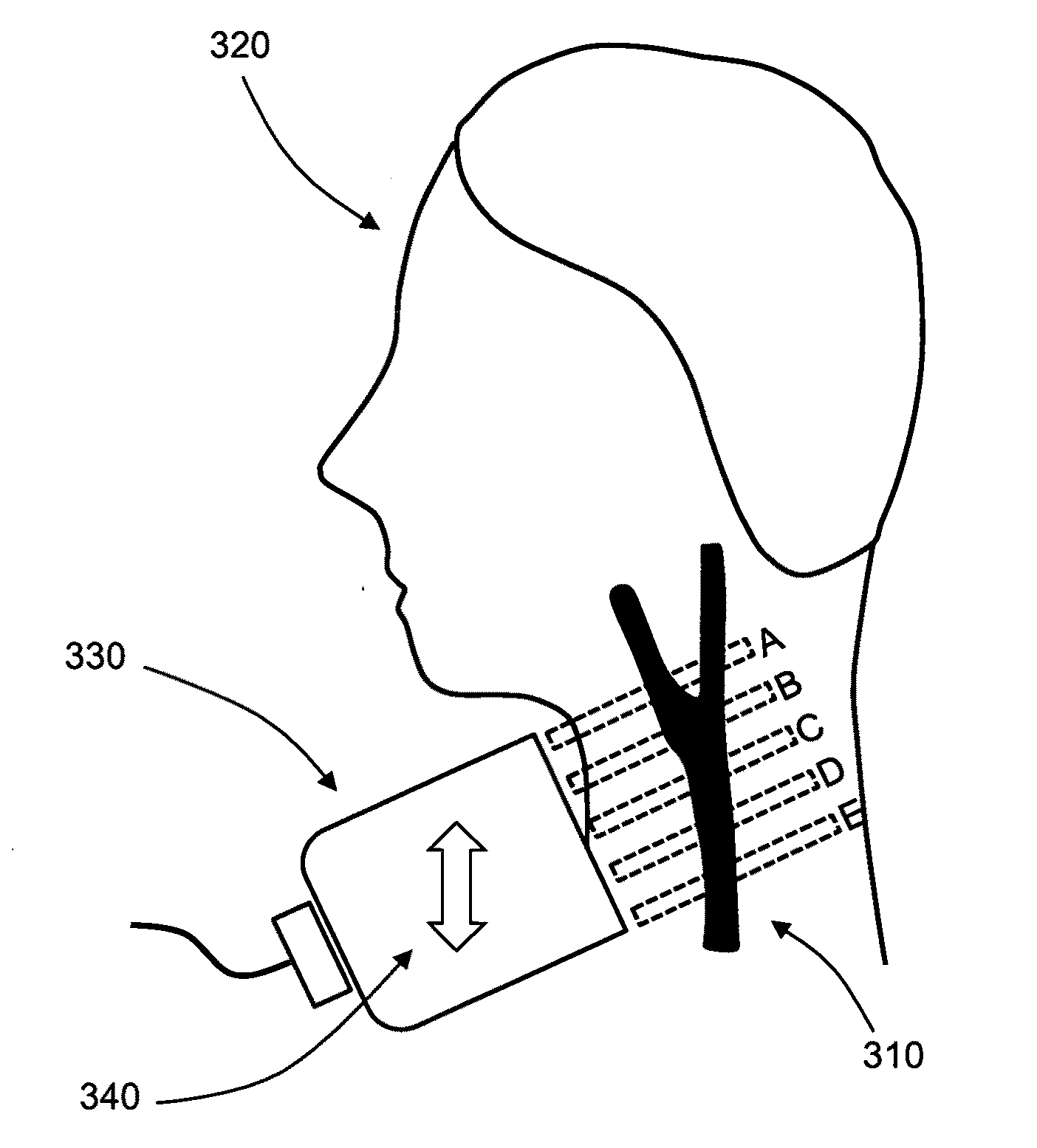
[0024]The present invention is directed to the measurement of peak blood velocities in a blood vessel and using a calculation of the Doppler angle to correct the measured PBVs. Preferred embodiments of the present invention utilize planar cross-sectional images of the blood vessel to determine the Doppler angle and PBVs. The present invention does not require three-dimensional or four-dimensional imaging techniques, which can be financially or computationally expensive, have great hardware demands, and require extensive processing and analysis. However, it is noted that the present invention can also be used in combination with three-dimensional or four-dimensional ultrasound techniques.
[0025]FIG. 3A shows an embodiment of the present invention for imaging the carotid artery 310 of a subject 320 with an ultrasound transducer 330. Though FIG. 3A and the examples herein describe imaging of the carotid artery 310 of a human subject 320, it is noted that the present invention can be applied to any blood vessel for any human or non-human subject. It is important to note that the ultrasound transducer 330 measures a set of spatially proximate ultrasound images A-E along the carotid artery 310. Each of the ultrasound images A-E is a planar cross-section of the carotid artery. Preferably, the ultrasound images A-E include at least all of the cross-sectional area of the blood vessel. Ultrasound imaging requires transmitting one or more ultrasound beams and receiving their reflections. The Doppler shifts of the transmitted and reflected beams are used to calculate a velocity map of the blood or other fluid in the image plane. In a preferred embodiment, the planar cross-sections transect the blood vessel with a transect angle less than approximately 45 degrees. Because Doppler shifts are accurately measured only when the blood flow has a significant component along the axis of the image planes, smaller transect angles are preferred.
[0026]FIG. 3B shows an example of the velocity maps imaged in FIG. 3A, where darker regions indicate greater velocities. By using velocity maps of the fluid imaged by the ultrasound transducer 330, the true PBV and Doppler angle ΘD can be determined. High peak blood velocity can be correlated with stenosis (i.e., constriction of the blood vessel). An uncorrected PBV can be identified in the planar cross-section velocity maps A-E. The location of the uncorrected PBV is generally located at or near one of the planar cross-sections. In an embodiment, the operator of the ultrasound transducer 330 can move the transducer approximately along the blood vessel axis to find the location of the uncorrected PBV. This translational movement is indicated by the arrow 340. It is noted that the translational movement 340 is significantly simpler than the combination of translations and rotations 150-170 necessary to operate existing devices, where the operator attempts to determine the Doppler angle ΘD simultaneously while finding the location of the PBV. Alternatively or in combination with translational movement 340 of the ultrasound transducer 330, the location of the uncorrected PBV can be found by extrapolation or interpolation of the set of velocity maps in the ultrasound images A-E.
[0027]To determine the Doppler angle ΘD for correcting the measured PBV, a high velocity center is identified in each of at least a subset of the ultrasound images A-E. The high velocity center can be identified by any technique, including based on a velocity-thresholded centroid, a velocity center of mass, or a location having the approximately highest velocity the velocity map. FIG. 4 shows the identified high velocity centers 410 for the ultrasound images A-E. The high velocity centers 410 are used to calculate the Doppler angle ΘD. In a preferred embodiment, a curve is fitted for the high velocity centers, where the fitted curve represents the direction of blood flow in the vessel. The direction ΘT of the peak blood velocity v is found in FIG. 4 by fitting a line to the high velocity centers 410. The Doppler angle ΘD between v and vD can then be calculated knowing the angle of construction of the ultrasound planes ΘK, and ΘT.
[0028]In an embodiment of the present invention, the fitted curve of the high velocity centers 410 is not a straight line. In certain embodiments, non-linear curves may more accurately represent the direction of blood flow, particularly when the imaged blood vessel has high curvature at the region of interest. When a non-linear curve is fit, the direction of the true PBV can be found based on a tangent of the curve at or near the location of uncorrected PBV.
[0029]It is noted that the present invention can also be applied to regions where the blood vessel bifurcates, such as in the carotid artery. FIGS. 3A-B show an example of imaging a bifurcating vessel. In an embodiment, bifurcations are accounted for by identifying multiple high velocity centers in each of at least one of the ultrasound images. For example, ultrasound image A of FIG. 3B shows that the blood vessel has likely bifurcated at a location between the planar cross-sections of image A and image B. When multiple high velocity centers are identified for each of at least one ultrasound image, one or more curves can be fitted to the high velocity centers of the set of ultrasound images. Different curves can be used to analyze the blood flow along the separate channels of the bifurcated vessel and can be used to calculate multiple Doppler angles.
[0030]In a preferred embodiment, the planar cross-sections of the set of ultrasound images are approximately parallel. Parallel cross-sections allow for simple calculation of the Doppler angle ΘD. In alternative embodiments, the cross-sections imaged by the ultrasound transducer are not parallel. In these embodiments, the angles between the planar cross-sections are preferably known and can be accounted for in computing the vessel direction ΘT required for calculating the Doppler angle ΘD. It is noted that though the set of ultrasound images shown in the figures have five ultrasound images, any number of images (therefore, any number of planar cross-sections) can be used.
[0031]FIG. 5 shows a flow chart of an embodiment of the present invention. The dashed box encloses the steps that can be automated, i.e. without human intervention, though manual overrides are possible in certain embodiments. For example, a processor or computer is used to automatically implement one or more of the following steps: determine an uncorrected peak velocity, identify high velocity centers, calculate the Doppler angle ΘD, correct the peak velocity based on the Doppler angle ΘD, and correlate the corrected peak velocity with a degree of stenosis. Automatic detection of stenosis allows non-specialists (e.g. nurses, medical assistants, etc.) to measure peak blood velocity and flag patients for further diagnosis. In an embodiment, an ultrasound transducer device of the present invention, a processor, and its associated software can be used as a part of a routine medical visit, such as a physical.
[0032]The present invention is also directed to a device for determining the peak blood velocity in a blood vessel. FIG. 6A shows an example device 600 having an array of ultrasound transducers 610 and the electronics 620 necessary to operate the transducers. FIG. 6B shows an exemplary embodiment of the transducer array 610. Preferably, the transducer array 610 is a two-dimensional rectangular array having a plurality of transducer elements 630. In other embodiments, the array can have another configuration, including a circular array, a one-dimensional array, an annular ring array, etc. In a preferred embodiment, the transducer elements 630 are capacitive micromachined ultrasound transducers (CMUTs). In an exemplary embodiment, the ultrasound transducer comprises multiple one-dimensional arrays implemented on a single substrate, wherein each of the one-dimensional arrays images one of the planar cross-sections.
[0033]In a preferred embodiment, the transducer array 610 is divided into a number of transducer sub-arrays 611-615. Each of the sub-arrays measures one of the ultrasound images. In other words, the transducer array is divided so that each sub-array is dedicated to measure a single planar cross-section of the blood vessel. By dividing the transducer array 610, the electronics 620 can be simplified. In an embodiment, the transducer array 610 includes multiple acoustic lenses 640, wherein each of the acoustic lenses 640 corresponds with one of the sub-arrays 611-615. An acoustic lens 640 determines the transect angle of the planar cross-section imaged by its corresponding sub-array. As described above, a transect angle less than about 45 degrees is preferred. In an embodiment, the transducer array 610 includes asymmetric acoustic lenses to set the transect angle.
[0034]The ultrasound transducer of the present invention can have any operating frequency. Generally, imaging resolution improves with greater operating frequency. However, higher frequencies are more limited by penetration depths than lower frequencies. In a preferred embodiment that can be used for carotid imaging, the transducers of device 600 operate at a frequency range within approximately 5-15 MHz. In an embodiment, the transducer elements 630 of the array 610 are spaced based on the acoustic wavelength corresponding to the operating frequency of the transducers. In particular, the element spacing can be about half of the acoustic wavelength to prevent unwanted grating lobe artifacts in the ultrasound images. In another embodiment, the operating frequency of the transducers is approximately 7 MHz, where the acoustic wavelength in tissue is approximately 200 μm. It is noted that the transducers can operate at operating frequencies outside of the indicated range and can have any element spacing.
[0035]Further details of the transducer array, CMUTs, and electronics of the device can be found in U.S. Provisional Patent Application 61/068,004 filed Mar. 3, 2008, which is incorporated herein by reference.
[0036]As one of ordinary skill in the art will appreciate, various changes, substitutions, and alterations could be made or otherwise implemented without departing from the principles of the present invention, e.g. the present invention can be applied to finding peak velocity of any fluid in any vessel and is not limited to blood velocity in blood vessels. Accordingly, the scope of the invention should be determined by the following claims and their legal equivalents.
PUM


Description & Claims & Application Information
We can also present the details of the Description, Claims and Application information to help users get a comprehensive understanding of the technical details of the patent, such as background art, summary of invention, brief description of drawings, description of embodiments, and other original content. On the other hand, users can also determine the specific scope of protection of the technology through the list of claims; as well as understand the changes in the life cycle of the technology with the presentation of the patent timeline. Login to view more.