

Ratchet driver
a ratchet and driver technology, applied in the field of ratchet drivers, can solve the problems of insufficient torsion and poor combination of ratchet drivers, and achieve the effects of convenient assembly and disassembly, effective pressing on the surface, and simple structur
- Summary
- Abstract
- Description
- Claims
- Application Information
AI Technical Summary
Benefits of technology
Problems solved by technology
Method used
Image

Examples
Embodiment Construction
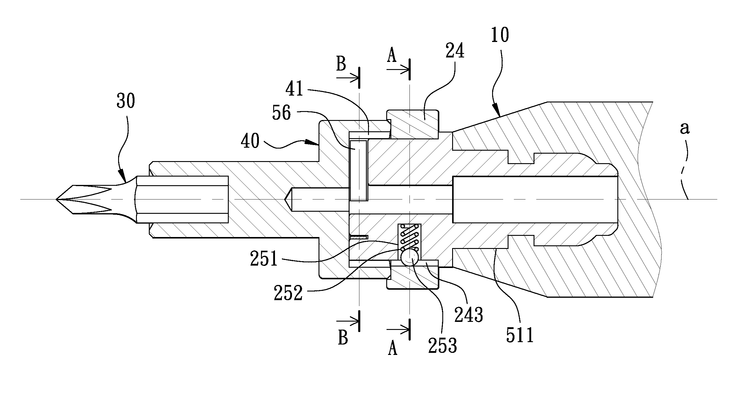
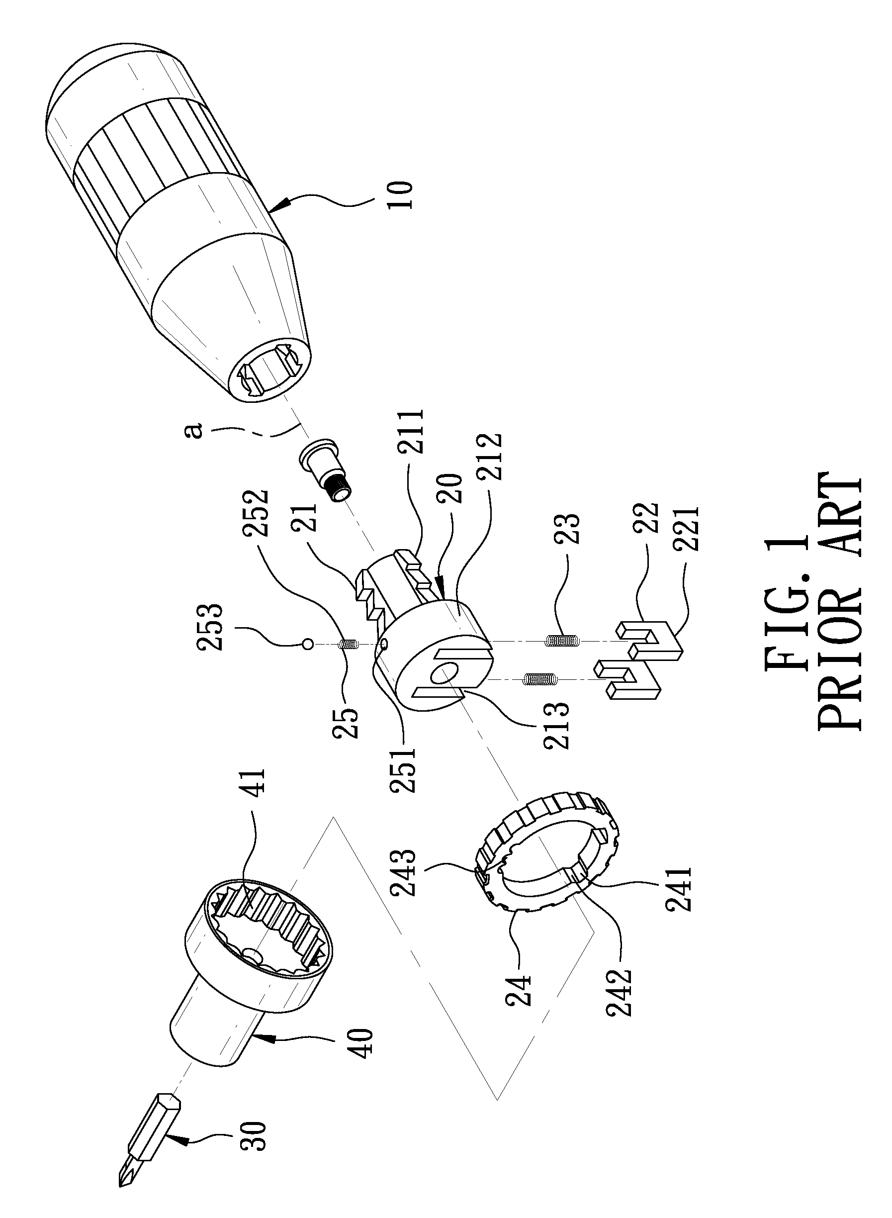
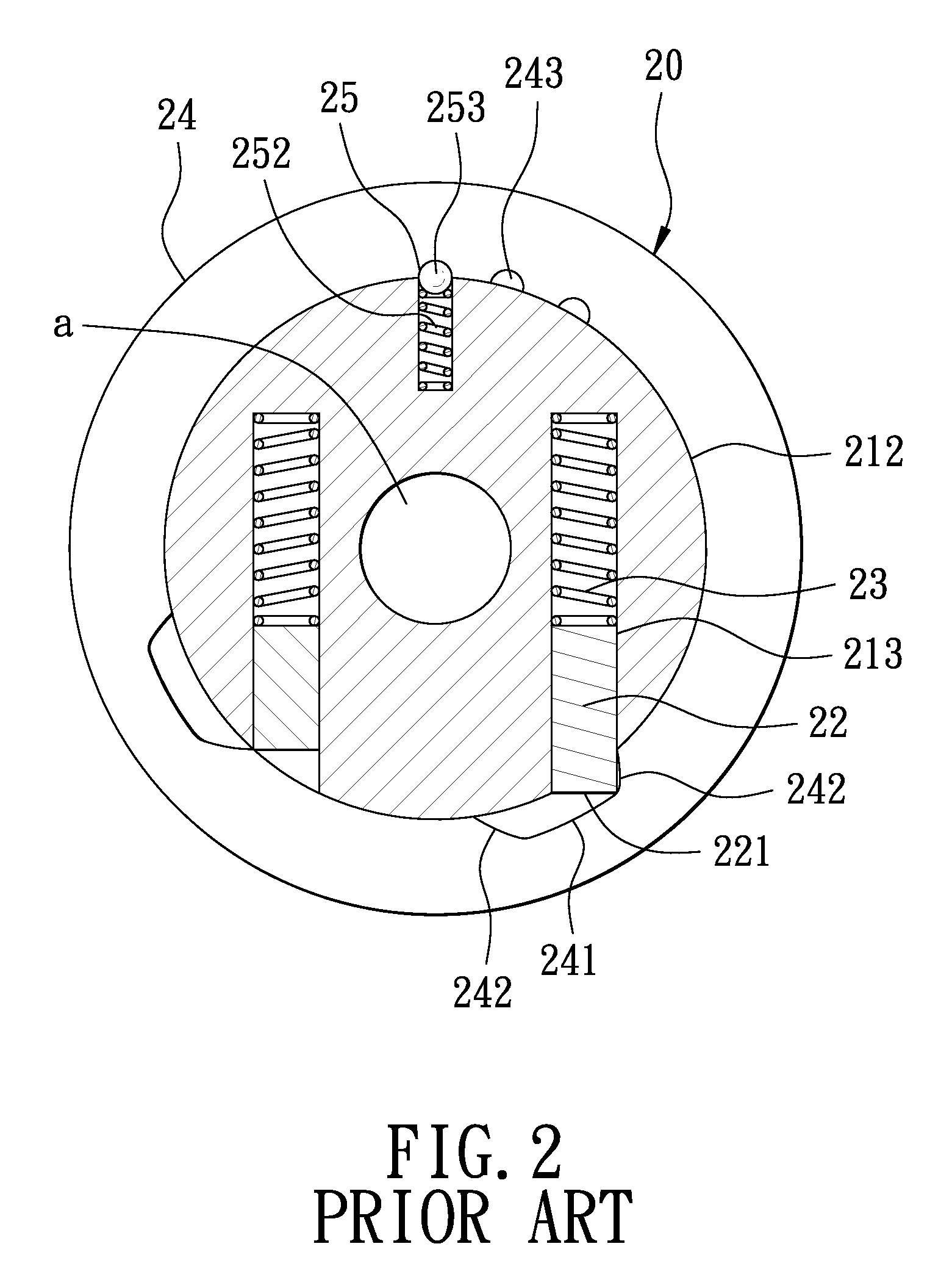
[0019]As shown in FIGS. 3 and 4, a preferred embodiment of a ratchet driver in the present invention has the same components as the conventional one does, except that the ratchet unit 20 in the conventional one is replaced with a ratchet unit 50. Thus, the ratchet driver of the invention is composed of the grip 10, the ratchet unit 50 installed with the grip 10 and the driving head 30 driven by the ratchet unit 50. The ratchet unit 50 includes a positioning base 51 provided with a central through hole (a), a connecting portion 511 formed at its one side for fixing with the grip 10, and a positioning portion 512 formed at another side for being mounted by the ratchet wheel 40. Two accommodating grooves 52 and 53 are respectively and axially formed at two sides of the central through hole (a), paralleling to each other for respectively fitting a locking piece 54 and 55, which are separated by an elastic element 56. The locking grooves 241 of the direction-changing ring 24 are formed t...
PUM
 Abstract
Description
Claims
Application Information