Chamber of a peristaltic pump for tire pressure adjustment

a peristaltic pump and chamber technology, applied in the direction of tyres, tyre beads, tyre measurements, etc., can solve the problems of poor operation, high production cost, high cost and complexity of devices, etc., and achieves short operating life, rapid wear and tear, and high fineness and/or fitting.

Inactive Publication Date: 2009-12-03
CODA INNOVATIONS SRO
View PDF15 Cites 72 Cited by
  • Summary
  • Abstract
  • Description
  • Claims
  • Application Information

AI Technical Summary

Benefits of technology

[0013]The chamber has an advantage of being at least partly ring-shaped, or at least partly torus, or at least partly helix. The chamber can be located in the space of the tire sidewall, at its bead; or it can be located in the ancillary structure inserted between the tire sidewall and at least one component of the assembly consisting of the rim, hub-cap, or support. In the efficient design, the ancillary structure with chamber is firmly connected to the rim or hub-cap, or with the tire sidewall. The ancillary structure containing the chamber is efficiently shaped for tight fitting with the tire sidewall from one side and shaped for fitting with the rim from the other side.
[0037]Approximately a half of the vehicles on the roads have at least one tire underinflated by more than 20 percent, which is considered as highly risky. An underinflated tire can keep track worse and overheats, which leads to its rapid wear and tear, and thus to the loss of grip, or even to its explosion. Besides these safety risks, the economic side is important too. An underinflated tire has shorter operating life and higher rolling resistance, which shows by increased fuel consumption of the vehicle. Since drivers generally tend to overlook this risk and do not deal with it, self-inflation will have great safety and economic impacts.

Problems solved by technology

The draw back of these solutions are high costs and complexity of the devices.
Disadvantages of these designs are high production costs, worse operation and mounting of the chamber and the related components into the wheel assembly, very high risk of breakage, crumbling and abrasion of the chamber walls in their compressing, and thus shortened chamber life expectancy as well as the tire safety.
Another disadvantage is difficult or unsolved joining of the individual chamber components; then the need for fundamental modifications in the tire chamber-type manufacturing method, and especially the fundamental modifications of the production machinery.
Yet another disadvantage is the need of production basically complete unique chamber assembly for each tire type and pressure.

Method used


Image

  • Chamber of a peristaltic pump for tire pressure adjustment
  • Chamber of a peristaltic pump for tire pressure adjustment
  • Chamber of a peristaltic pump for tire pressure adjustment

Examples


example 1

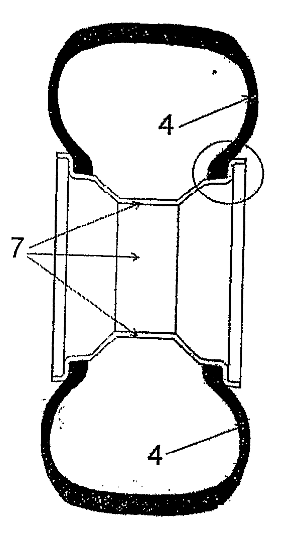
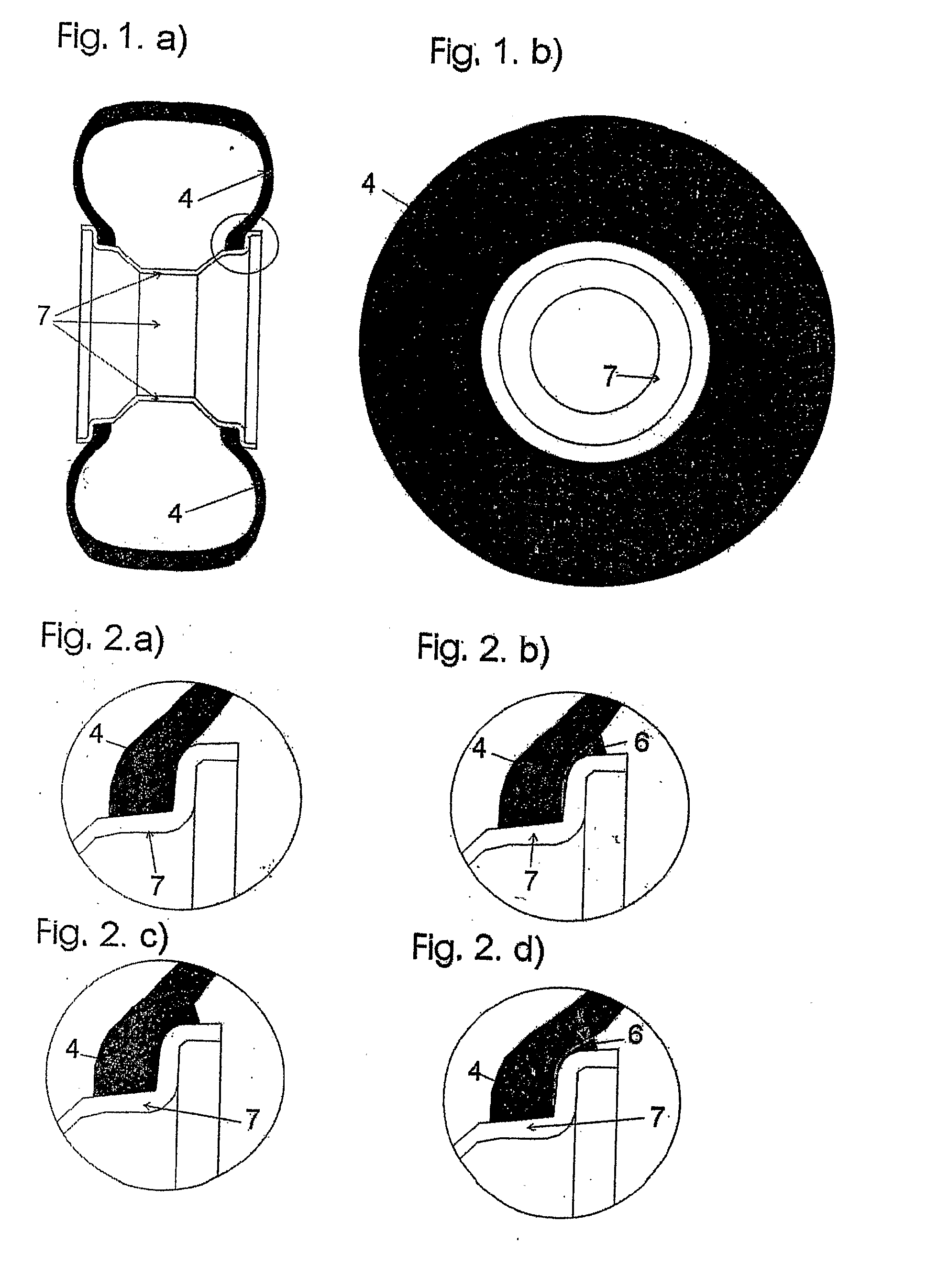
[0052]The chamber 1 with shape memory for pressure correction in the tire, which is a part of the tire or adjacent to the tire wall and is connected with the internal space of the tire at one end and with the exterior environment at the other end, has the shape of a curved hollow channel, with its enclosing wall partly formed by the pair of surfaces 10 lengthwise coplanar with the chamber 1 (channel) under the angle of α=2 to 15°. The angle α>0° is on the contacting edge of these surfaces 10 located on the further side from the center of the chamber 1 cross-section. The chamber 1 is placed in the area of the tire side wall 4 at its bead.

[0053]When manufacturing the chamber 1 a flat matrix 9 with a shaped protrusion and with a width of 0.8 mm and thickness of 0.02 mm, is inserted between the layers forming the tire side wall 4 before vulcanization, then the vulcanization is performed and the inserted matrix 9 is extracted as a whole towards the center axis 2 of the tire 4. The thickn...

example 2

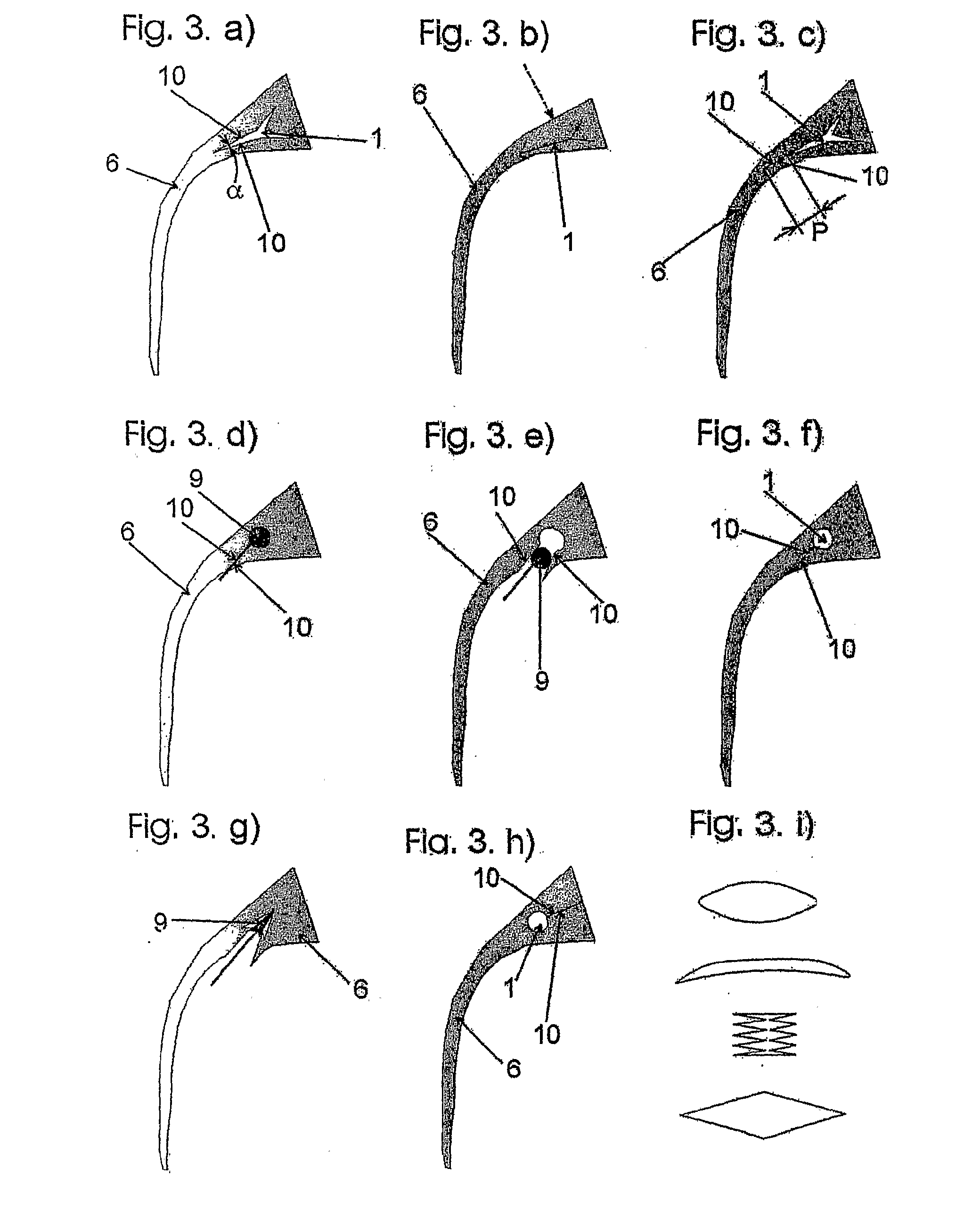
[0061]FIG. 3. a) shows the ancillary structure 6 containing the chamber 1 with the cross-section in the shape of a three-pointed star. This part of the chamber 1 is placed on the outside side wall of the tire 4 above the tire 4 bead and the rim 7. The tire 4 is not shown here and the chamber 1 is shown in an unloaded condition. There is a sharp angle α on the surfaces 10 comprising the wall of one of the points. The sharp angle will ensure the hermetical sealing of the walls forming the chamber 1 upon deformation of the chamber 1, while there is minimum bending and tension in the walls, which reduces the overall tension and material stress in the chamber 1 walls. The FIG. 3. b) shows a cross-section through the chamber 1 under load, the walls of the chamber 1 adjoin each other in the loaded point, the chamber 1 is blind and has the zero cross-section area of the chamber 1 in this point. The direction of deformation caused by load is indicated by a broken arrow.

[0062]The chamber 1 wi...

example 3

[0066]The chamber 1 can be manufactured by pressing in the matrix 9 between the walls of the chamber 1 and subsequent extraction of the matrix 9. The extension of the surfaces 10 outside the chamber 1 itself under the zero angle between the surfaces 10 then allows simple extraction of the matrix 9 in the manufacture of the chamber 1.

[0067]FIG. 3. d) shows the manufacture of the chamber 1 with a circular profile. The partly circular matrix 9 is impressed in the material of future chamber 1 walls; it is then extended outside the circular cross-section of the chamber 1 and led out of the ancillary structure 6. After pressing out, this extension will make parallel surfaces 10 passing through the chamber wall up to the point outside of the ancillary structure 6. Thus it will create a passage for extraction of the impressed matrix 9. Extraction of the matrix 9 is shown on FIG. 3e).

[0068]After fitting the ancillary structure 6 and tire 4 onto the rim 7, these extended surfaces 10 will pres...


PUM

PropertyMeasurementUnit
angleaaaaaaaaaa
thicknessaaaaaaaaaa
widthaaaaaaaaaa

Abstract

A chamber (1) that works as a peristaltic pump for the pressure correction in the tire (4), which is a part of the tire (4) or of an ancillary structure (6) placed between the rim (7) and the tire bead (4) and is connected with the tire (4) internal space at one end and with the external environment at the other end. The chamber (1) is in the shape of a curved hollow channel, where at least one enclosing wall is at least partially formed by at least a pair of surfaces (10) coplanar with the longitudinal direction of the chamber (1). When the tire is mounted on the rim, the pair of surfaces (10) are pressed together thus hermetically closing the chamber (1). When the chamber (1) is closed during rotation of the wheel, the surfaces (10) can slightly slide on one another taking internal wall tensions onto themselves thus decreasing the possibility of wall damage through ripping. A method of producing the chamber (1) is also disclosed.

Description

TECHNICAL FIELD[0001]The invention regards a chamber with shape memory for tire pressure adjustment, which is a part of the tire or is adjacent to the tire wall and connected with the tire internal space at one end and with the exterior environment at the other end. It also concerns the production method of the chamber and tire and rim with this chamber.BACKGROUND ART[0002]Different solutions for pressure maintenance in the tire under operation are used in technical practice. These are for example tires fitted with an air intake, connected to an external source of pressurized air. The draw back of these solutions are high costs and complexity of the devices.[0003]There are also self-inflating tires. For example, the model type of a self-inflating tire is described in pending patents CZ PV 2002-1364 and CZ PV 2001-4451. The air feed chamber is located in the tire wall or adjacent to it. The chamber is periodically completely compressed or broken, with progressive rolling deformation ...

Claims


Application Information

Patent Timeline
Patent Type & Authority Applications(United States)
IPC IPC(8): B60C23/00B29D30/08B60C29/02
CPCB60C23/12B60C15/06B60C23/123B60C23/135
Inventor HRABAL, FRANTISEK
Owner CODA INNOVATIONS SRO
Why Eureka
Try Eureka