
Optical signal waveform shaping apparatus

a waveform shaping and optical signal technology, applied in optics, instruments, electromagnetic transmission, etc., can solve the problems of degraded optical signal waveform, “1” level noise of optical signal, etc., and achieve the effect of efficiently shaping the waveform of degraded optical signal

Inactive Publication Date: 2008-11-11
FUJITSU LTD
View PDF30 Cites 15 Cited by
  • Summary
  • Abstract
  • Description
  • Claims
  • Application Information

AI Technical Summary

Benefits of technology

[0009]It is an object of the present invention to provide an optical waveform shaping apparatus for efficiently shaping a waveform of a degraded optical signal.
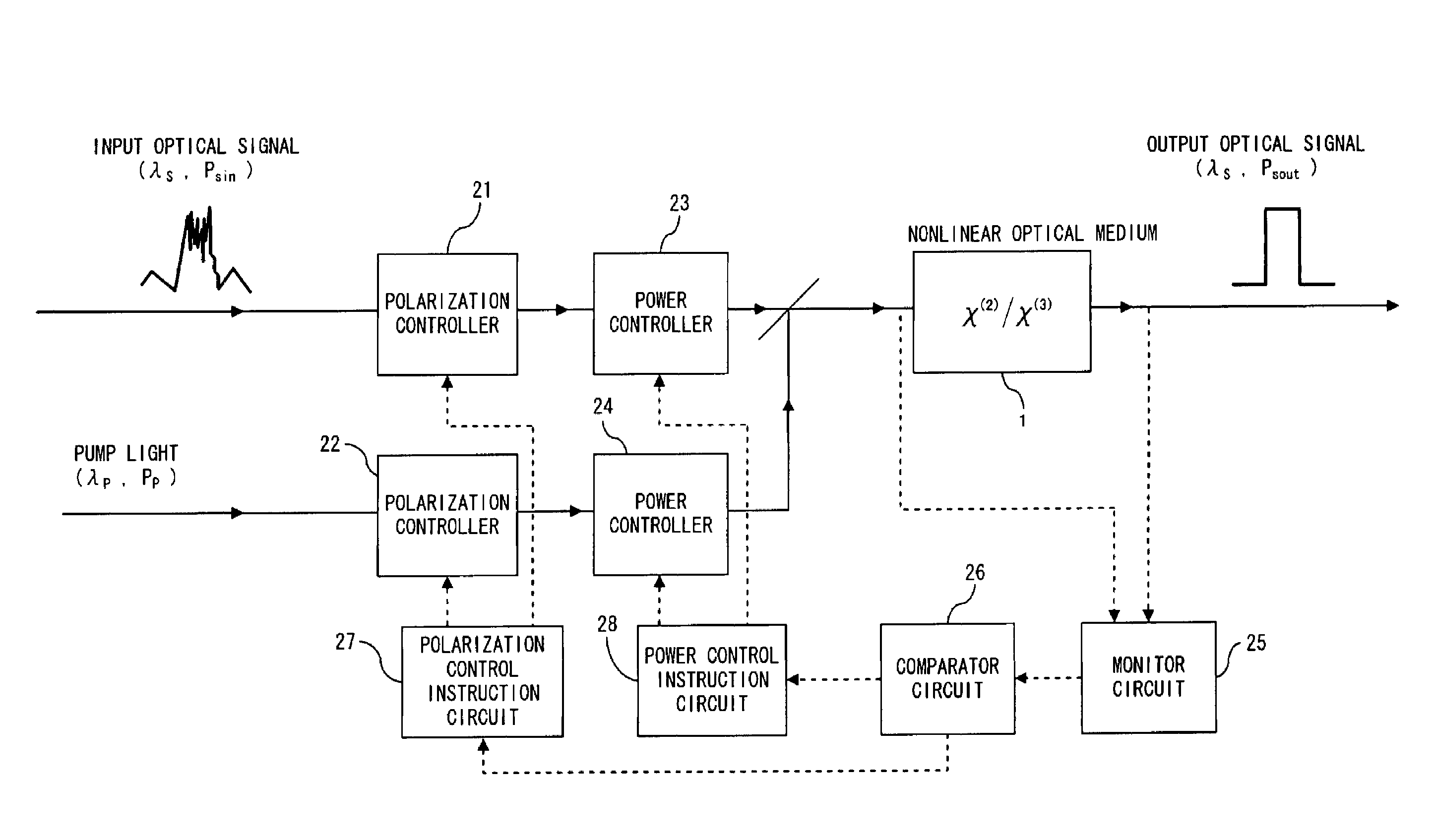
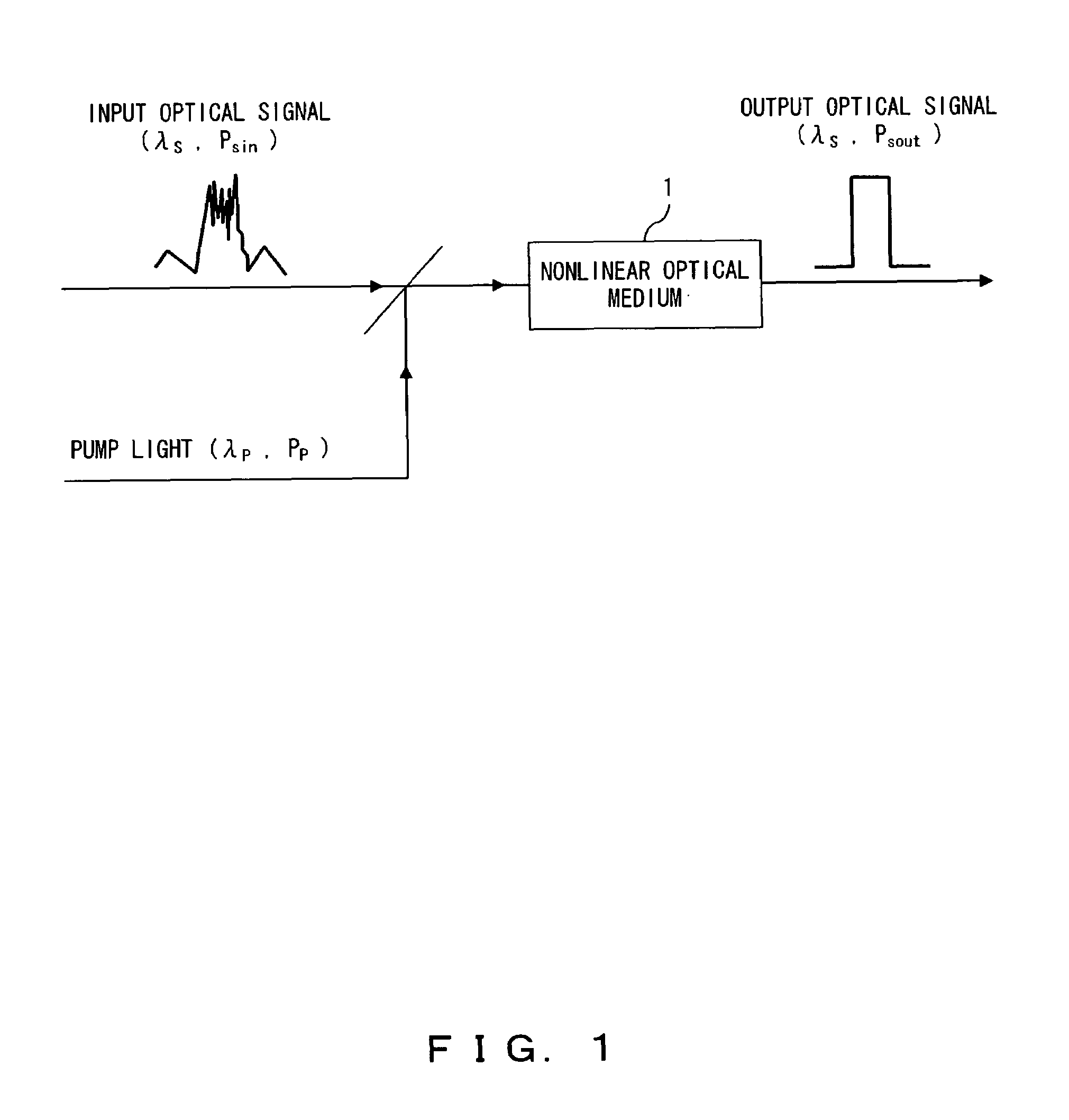
[0011]The optical signal is parametrically amplified by the pump light in the nonlinear optical medium. However, if the input power of the optical signal is increased, the pump light power is consumed in order to generate four-wave mixing, and the parametric gain reaches saturation. This saturation enables the realization of the optical limiter function and suppresses the “1” level noise of the optical signal.
[0012]The optical waveform shaping apparatus may further comprise a saturable absorber in a previous stage or a subsequent stage of the nonlinear optical medium. Using the saturable absorber, “0” level noise of the optical signal can be suppressed.
[0013]According to the present invention, it is possible to provide an optical waveform shaping apparatus for efficiently shaping the waveform of a degraded optical signal. Through the use of the optical waveform shaping apparatus of the present invention in an optical communication system, communication quality may be improved (e.g., improving the optical signal-to-noise (S / N) ratio).

Problems solved by technology

However, if the input power of the optical signal is increased, the pump light power is consumed in order to generate four-wave mixing, and the parametric gain reaches saturation.

Method used


Image

  • Optical signal waveform shaping apparatus
  • Optical signal waveform shaping apparatus
  • Optical signal waveform shaping apparatus

Examples


first example

[0073]In the first example, the optical waveform shaping apparatus of the present invention is applied to an optical switch having an amplification function. This kind of optical switch is, for example, realized by providing a polarizer in the subsequent stage of the nonlinear optical medium 1 of the optical waveform shaping apparatus shown in FIG. 7.

[0074]FIG. 8A-FIG. 8C are diagrams explaining operations of the optical switch of the first example. In the following description, assume that the optical signal Es (wavelength: λs, peak power: Ps) and optical control pulse Ep (wavelength: λp, peak power: Pp) serving as the pump light, are input to an optical fiber (HNLF) 31 serving as the nonlinear optical medium.

[0075]In the subsequent stage of the optical fiber 31, a polarizer 32 is provided. A linear polarization component in a direction of the polarization main axis of the polarizer 32 alone in the optical signal output from the optical fiber 31 is transmitted through the polarizer...

second example

[0081]The optical waveform shaping apparatus of the second example comprises a saturable absorber 41 in the previous or subsequent stage of the nonlinear optical medium 1 of the above waveform shaping apparatus, as shown in FIG. 9. The saturable absorber 41 suppresses the OFF level fluctuation of an optical signal. Note that the saturable absorber 41 can be realized by a semiconductor amplifier, a Mach-Zehnder interferometer optical fiber switch, a nonlinear optical loop mirror (NLOM) switch, or similar means, for example.

third example

[0082]One of the causes of quality deterioration of a phase-modulated optical signal or a frequency-modulated optical signal is such that intensity noise (and intensity fluctuation) is converted into phase noise by the nonlinear optical effect in an optical fiber. Therefore, suppression of the intensity noise (and intensity fluctuation) of an optical signal by using the optical waveform shaping apparatus of the present invention is effective for quality improvement of a phase-modulated optical signal or a frequency-modulated optical signal.

[0083]FIG. 10 is an example where the optical waveform shaping apparatus of the present invention is applied to a communication apparatus for optical communication system (e.g. an optical receiver or optical repeater). In this example, a system in which an optical DPSK signal is transmitted via an optical fiber transmission path is introduced. Assume that the optical wavelength of the optical DPSK signal is “λs”.

[0084]In the communication apparatu...


PUM

PropertyMeasurementUnit
transmission distanceaaaaaaaaaa
angleaaaaaaaaaa
angleaaaaaaaaaa

Abstract

An optical signal and pump light are input to a nonlinear optical medium. In the nonlinear optical medium, the optical signal is amplified with a nonlinear effect caused by the pump light. A monitor circuit monitors parametric gain in the nonlinear optical medium. A first power controller increases input power of the optical signal so that the gain reaches saturation. A second power controller controls input power of the pump light so as to obtain a desired gain.

Description

BACKGROUND OF THE INVENTION[0001]1. Field of the Invention[0002]The present invention relates to a waveform shaping apparatus for, among other purposes, shaping a waveform of an optical signal being degraded by for example transmission in an optical fiber.[0003]2. Description of the Related Art[0004]In conventional optical communication systems, the accuracy of the chromatic dispersion control of a transmission optical fiber and the characteristics of an optical amplifier amplifying an attenuated optical signal are primary factors which determine the limits of transmission speed (bitrate of data) and transmission distance. A configurations using a transmission line with an alternating arrangement of a normal dispersion fiber and an anomalous dispersion fiber or a configuration using a chromatic dispersion compensator (such as a dispersion compensation fiber) are well-known technologies for compensating for waveform distortion caused by long distance transmission. An optical amplifie...

Claims


Application Information

Patent Timeline
Patent Type & Authority Patents(United States)
IPC IPC(8): G02F1/39H04B10/17
CPCH04B10/299
Inventor WATANABE, SHIGEKI
Owner FUJITSU LTD
Learn More