Eureka AIR delivers breakthrough ideas for toughest innovation challenges, trusted by R&D personnel around the world.

Beam shaping device

a beam shaping and beam technology, applied in non-linear optics, instruments, optics, etc., can solve the problem of random scattering of this device that is not well suited for controlled beam shaping, and achieve the effect of efficient shaping

Inactive Publication Date: 2010-08-19
KONINKLIJKE PHILIPS ELECTRONICS NV
View PDF3 Cites 14 Cited by
  • Summary
  • Abstract
  • Description
  • Claims
  • Application Information

AI Technical Summary

Benefits of technology

[0005]In view of the above-mentioned and other drawbacks of the prior art, a general object of the present invention is to provide an improved beam shaping device, in particular a beam shaping device capable of more efficient shaping of a beam of light passing therethrough.
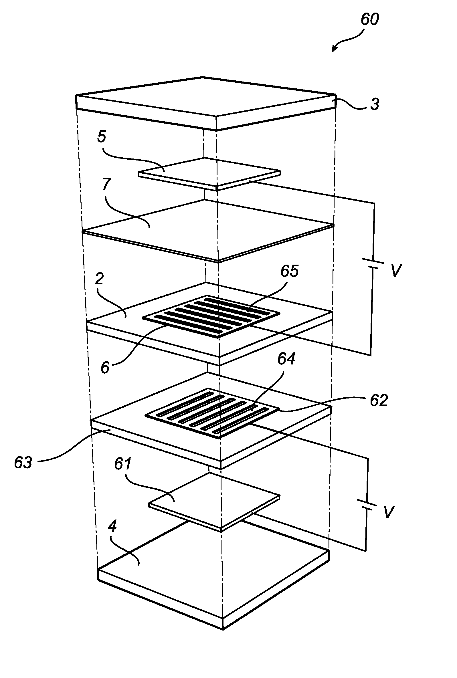
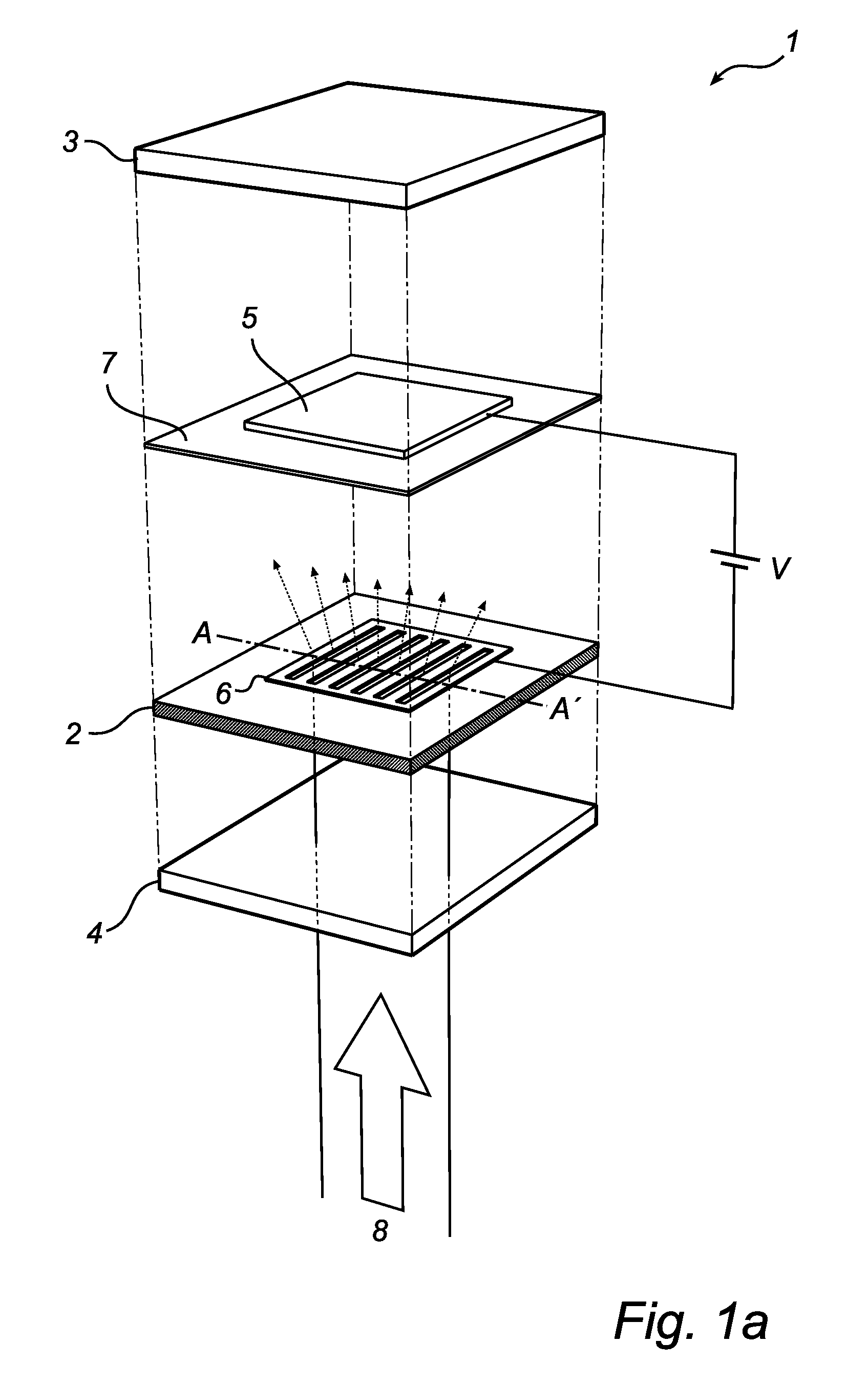
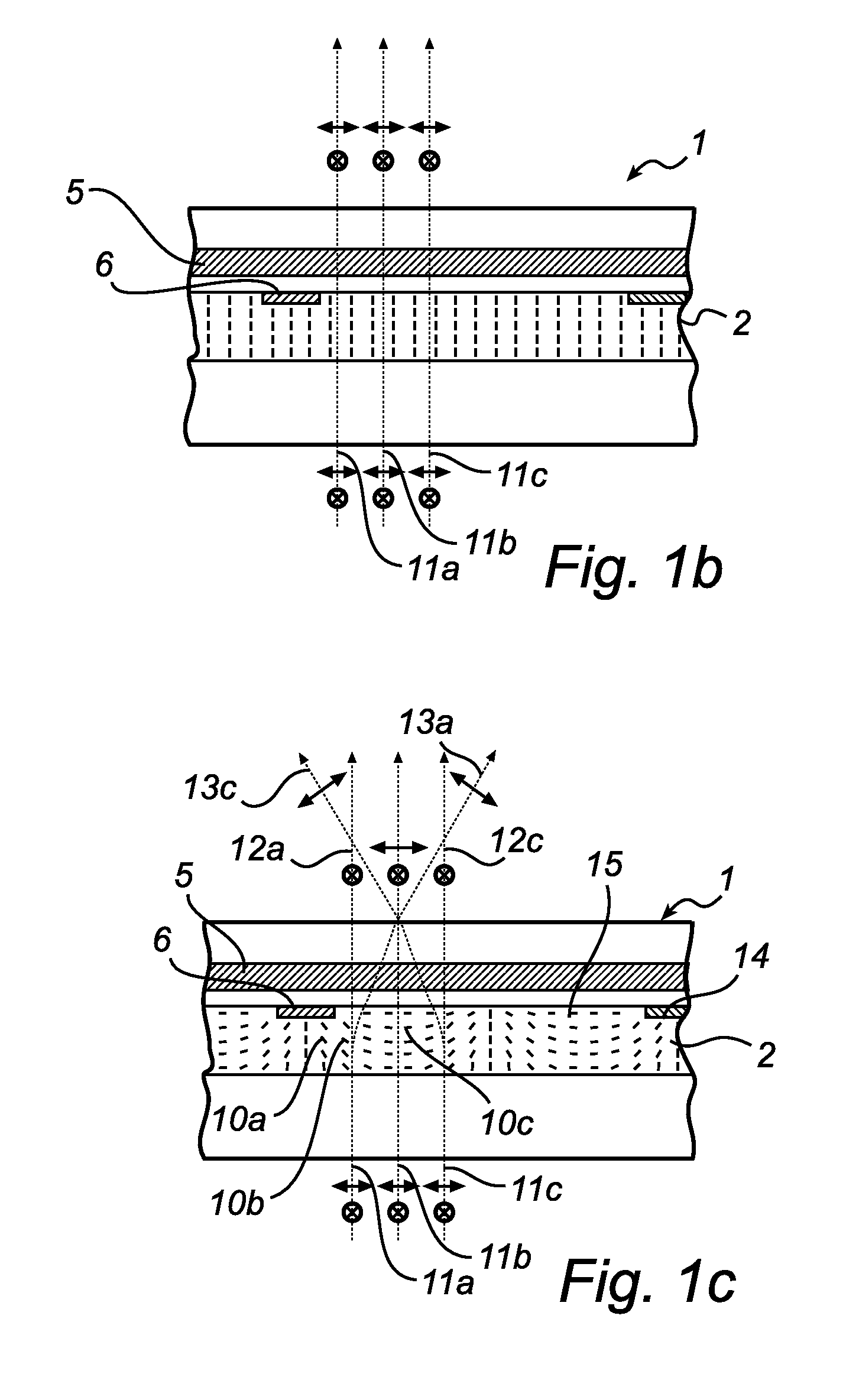
[0006]According to the present invention, these and other objects are achieved through a beam shaping device comprising first and second substrates, a liquid crystal layer sandwiched between the substrates, and a first electrode layer provided on a side of the first substrate facing the liquid crystal layer. The beam shaping device is controllable between beam shaping states, each permitting passage of light through the beam shaping device. The beam shaping device further comprises an insulating layer covering the first electrode layer, and a second electrode layer provided on top of the insulating layer. The second electrode layer comprises a conductor pattern exposing a portion of the insulating layer. The beam shaping device is configured in such a way that application of a voltage between the first and second electrode layers causes liquid crystal molecules comprised in a portion of the liquid crystal layer corresponding to the exposed portion of the insulating layer to tilt in a plane perpendicular to the liquid crystal layer, resulting in a local refractive index gradient, thereby enabling shaping of a beam of light passing through the beam shaping device.
[0007]The liquid crystal layer may comprise any kind of liquid crystal molecules, and may be in any one of its phases. The nematic phase is, however, preferred due to its relatively low viscosity as compared with other liquid crystal phases such as the smectic phase. In this way shorter switching times can be obtained. The liquid crystal layer may further comprise a liquid crystal composite containing polymers.

Problems solved by technology

Although being relatively compact and providing electrically controllable beam shaping, the beam shaping device disclosed in EP 0 578 827 suffers from loss of light due to backscattering Moreover, the random scattering of this device is not well suited for controlled beam-shaping.

Method used


Image

  • Beam shaping device
  • Beam shaping device
  • Beam shaping device

Examples


Embodiment Construction

[0049]In the following description, the present invention is described with reference to a beam shaping device having a homeotropically aligned liquid crystal layer—the liquid crystal (LC) molecules comprised in the LC layer are oriented perpendicular to the substrates when no voltage is applied to the electrodes. It should be noted that this by no means limits the scope of the present invention, which is equally applicable to beam shaping devices in which the liquid crystal molecules are aligned in any other way, such as a planar orientation in which the LC-molecules are oriented in a plane parallel with the substrates. In this orientation, the LC-molecules may be aligned in parallel with or perpendicular to the electrodes, or have a hybrid orientation where the LC molecules have a first orientation adjacent to the first substrate and a second orientation, orthogonal to the first orientation, adjacent to the second substrate.

[0050]Furthermore, in order not to obscure the present in...


PUM

PropertyMeasurementUnit
thicknessaaaaaaaaaa
widthaaaaaaaaaa
thicknessaaaaaaaaaa

Abstract

A beam shaping device (1; 50; 60) comprising first (3) and second (4) substrates, a liquid crystal layer (2) sandwiched between the substrates, and a first electrode layer (5; 51) provided on a side of the first substrate (3) facing the liquid crystal layer (2). The beam shaping device is controllable between beam shaping states, each permitting passage of light through the beam shaping device, and further comprises an insulating layer (7) covering the first electrode layer (5; 51) and a second electrode layer (6; 53) provided on top of the insulating layer. The second electrode layer (6; 53) comprises a conductor pattern exposing a portion of the insulating layer (7). The beam shaping device is configured in such a way that application of a voltage (V) between the first (5; 51) and second (6; 53) electrode layers causes liquid crystal molecules comprised in a portion of the liquid crystal layer (2) corresponding to the exposed portion of the insulating layer to tilt in a plane perpendicular to the liquid crystal layer, resulting in a local refractive index gradient, thereby enabling shaping of a beam (8) of light passing through the beam shaping device.

Description

TECHNICAL FIELD[0001]The present invention relates to a beam shaping device which is controllable between beam shaping states, each permitting passage of light through the beam shaping device.BACKGROUND OF THE INVENTION[0002]The ability to control the shape of a beam of light emitted by a light source is desirable in many applications ranging from general lighting to special lighting applications. Some examples are video flash, with beam shaping in combination with zooming, spot lights, flash lights, interior lights, head lamps and interior lamps.[0003]Conventionally, this beam shaping is achieved by mechanical beam shaping devices, such as mechanically controllable zoom lens arrangements. Recently, more compact beam shaping devices, utilizing the controllable properties of liquid crystal materials have been developed. An example of such a beam shaping device is disclosed in EP 0 578 827, where a liquid crystal light regulating plate scatters a desired amount of light emitted from a...

Claims


Application Information

Patent Timeline
Patent Type & Authority Applications(United States)
IPC IPC(8): G02F1/1343
CPCG02F1/134363G02F2201/122G02F2001/133742G02F1/29G02F1/133742
Inventor VAN BOMMEL, TIESHIKMET, RIFAT ATA MUSTAFAKRAAN, THOMAS CASPARDESSAUD, NATHALIE MAGALI DANIELLESTROMER, JAN FRANK
Owner KONINKLIJKE PHILIPS ELECTRONICS NV
Why Eureka
Eureka Blog
Learn More