Shape measurement method of synthetically combining partial measurements

a technology of partial measurement and shape measurement, applied in the field of measurement technique, can solve the problem of low accuracy level, achieve the effect of simple method, accurate determination, and efficient synthesizing of overall shap

Inactive Publication Date: 2009-12-10
CANON KK
View PDF12 Cites 15 Cited by
  • Summary
  • Abstract
  • Description
  • Claims
  • Application Information

AI Technical Summary

Benefits of technology

[0056]Thus, according to the present invention of this application, the positional displacements of the partial measurement data can be accurately determined without using the concept of overlap region so that the problems (1) through (4) that are attributable to the use of one or more than one overlap regions.
[0057]In addition to the above advantage, the present invention provides an advantage that the overall shape can be synthesized efficiently by a simple method.
[0058]Further, the present invention can correct the systematic error of a measuring machine by adding the systematic error to parameters, enabling to improve the measurement accuracy.
[0059]The present invention also provides an effect of preventing the instability of computations that arise depending on the shape of the workpiece.
[0060]The present invention also enables to stably computationally determine the shape of the workpiece if it includes one or more than one shape errors having a high spatial frequency.

Problems solved by technology

However, the above-described known stitching technique is developed on the basis of interference measurements and new problems as listed below arise when it is extended to measurements using coordinate measuring machines.
In other words, new problems as listed below arise when measurement data show differences of magnitudes that are remarkable if compared with ever.
(1) The accuracy level is low because overlap regions cannot be determined highly accurately.

Method used


Image

  • Shape measurement method of synthetically combining partial measurements
  • Shape measurement method of synthetically combining partial measurements
  • Shape measurement method of synthetically combining partial measurements

Examples


first embodiment

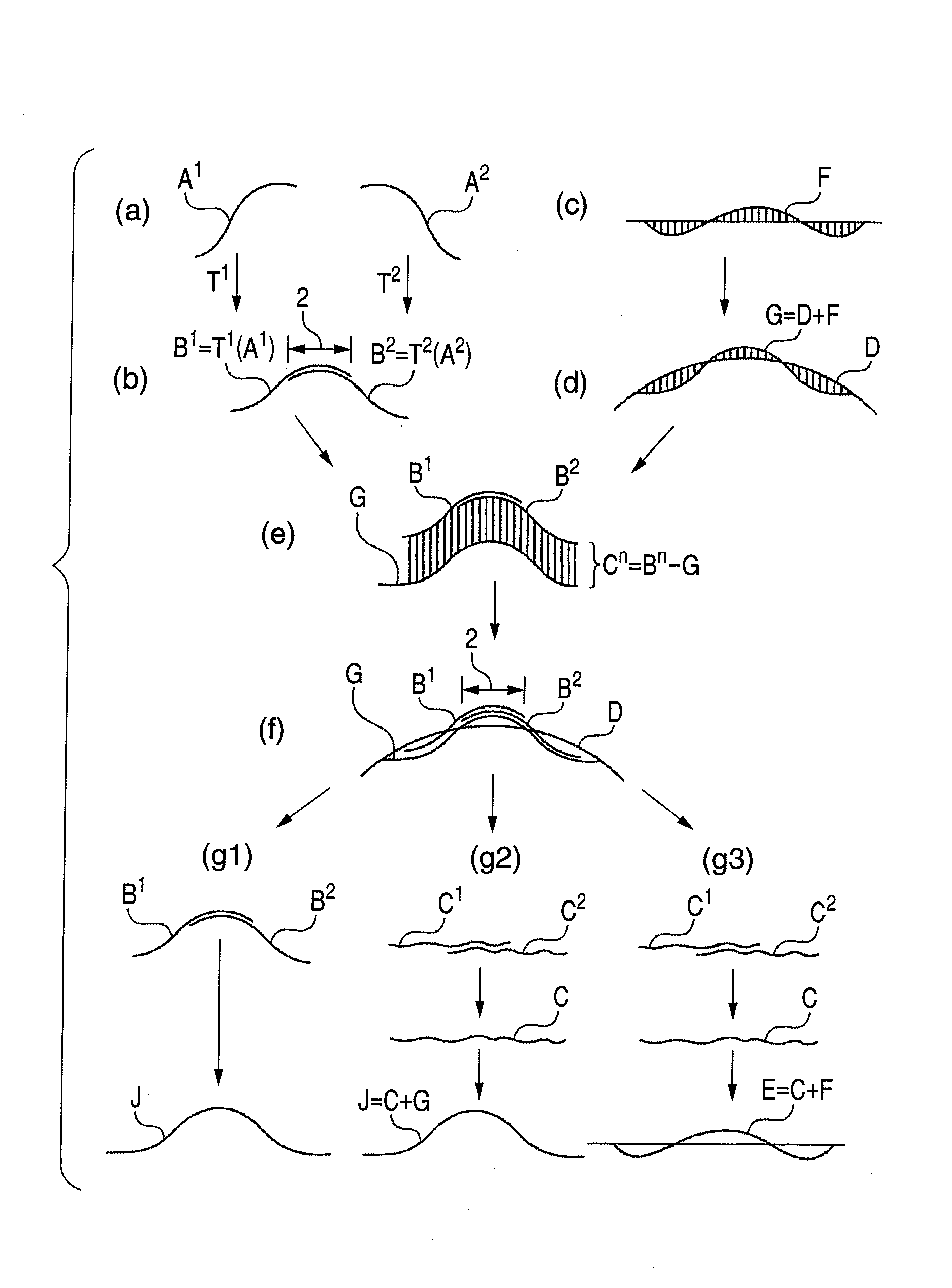
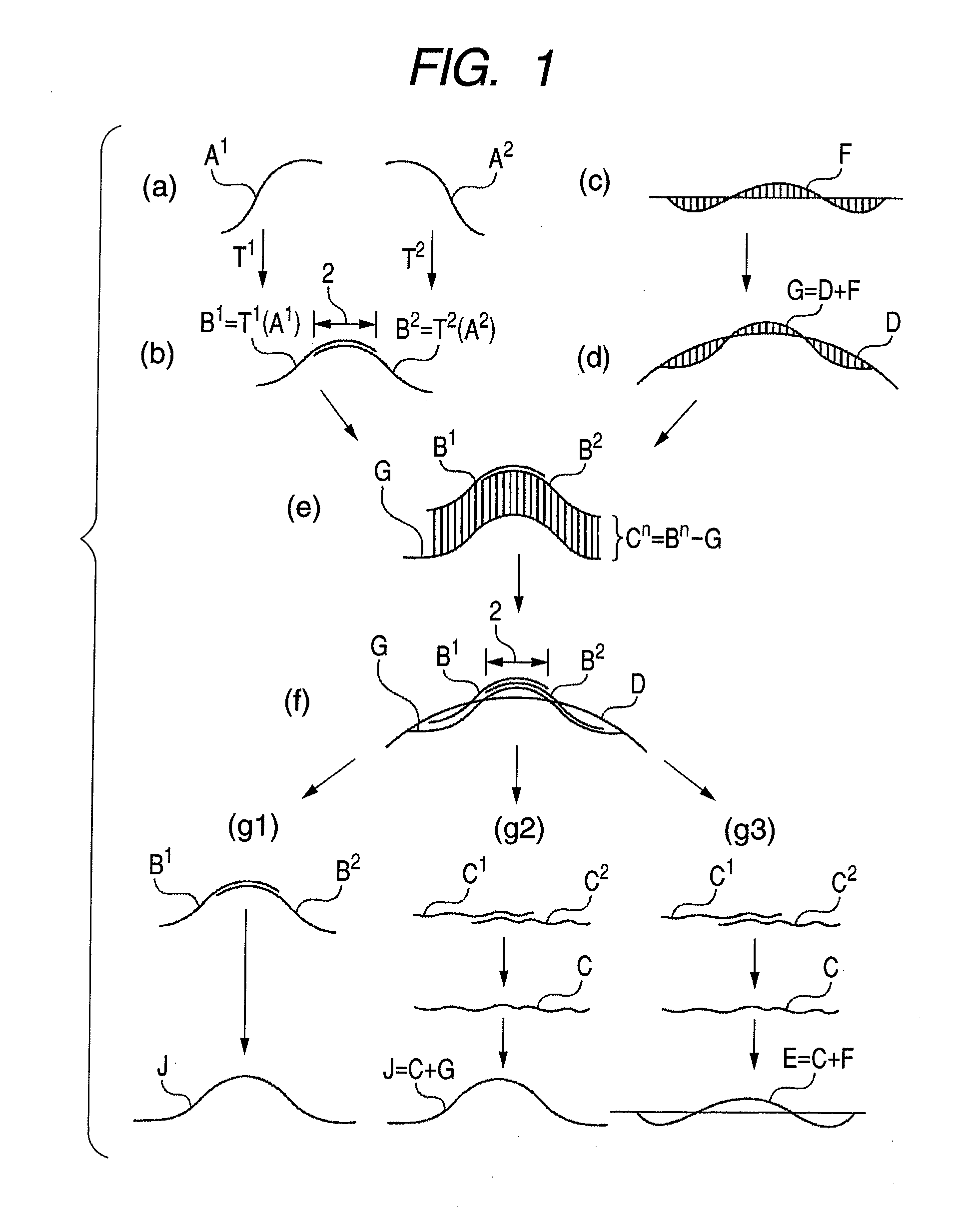
[0077]Now, the shape measurement method in the first aspect of the present invention will be described in detail on a step by step basis by referring to (a) to (g3) of FIG. 1. An instance of connecting two sets of cross section data will be described below for the purpose of simplicity. In this embodiment, first and second parameters are employed. The first parameter will be referred to as coordinate transformation parameter because it relates to coordinate transformation. The second parameter will be referred to as shape parameter because it relates to an approximate error shape.

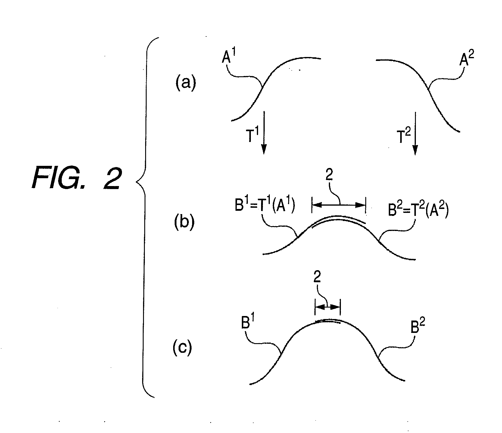
[0078]Step (a): Collecting partial measurement data respectively from a plurality of partial regions of a workpiece

[0079]Step (a) will be described by referring to part (a) of FIG. 1. In (a) to (g3) of FIG. 1, A1 and A2 represent the partial measurement data collected respectively from two different measurement regions. In the case of a coordinate measuring machine, partial measurement data are three-dimens...

second embodiment

[0111]Now, the second aspect of the present invention will be described in detail also by referring to (a) to (g3) of FIG. 1. When connecting plural sets of partial measurement data by means of the coordinate transformation parameters and the shape parameter that are optimized, one of the steps (g1), (g2) and (g3) described below can be used.

[0112]Step (g1): Making plural sets of partial measurement data that are subjected to coordinate transformations overlap each other and transforming them into an overall shape.

[0113]Step (g1) will be described by referring to part (g1) of FIG. 1. The alignment of the plural sets of partial measurement data should be completed by step (f). Thus, as a result, the difference of measurement data, or the mismatch, in the overlap region should be small as described above. As illustrated, the partial measurement data B that are subjected to coordinate transformation are made to overlap each other and transformed into an overall shape J.

[0114]Step (g2):...

third embodiment

[0119]The third aspect of the present invention relates to systematic errors. This will be described in detail by referring to (a), (b), (c), (d), (e), (f), (g1), (g2), (g3), (h) and (j) of FIG. 5. A systematic error is an error that a measuring machine intrinsically has. Measurement errors typically include errors that vary from measurement to measurement and those that do not vary and systematic errors belong to the latter. Systematic errors should be measured and corrected by means of a certain method. According to the present invention, a systematic error can be corrected by making it included in the parameters for optimization. In (a), (b), (c), (d), (e), (f), (g1), (g2), (g3), (h) and (j) of FIG. 5, step (a) is a step for obtaining measurement data. Note that A1 and A2 are measurement data that include a systematic error.

[0120]Step (h): Defining a systematic error parameter.

[0121]Now, step (h) will be described by referring to part (h) of FIG. 5. Symbol γ represents systematic...


PUM


Abstract

Coordinate transformation parameters are adopted at the time of synthetically combining partial measurement data so as to eliminate the setting error that can get in when a workpiece is set in position on a measuring machine. Then, a shape parameter is adopted to estimate the approximate error shape of the entire workpiece and the approximate error shape is removed from the measurement data. As a result, the residuals are reduced if the measurement data are those of three-dimensional sequences of points. Differences are small when small residuals are compared so that the mismatch is reduced. According to the present invention, the entire measurement data can be synthetically combined without using the conventional concept of overlap.

Description

BACKGROUND OF THE INVENTION[0001]1. Field of the Invention[0002]This invention relates a measurement technique of synthetically combining plural sets of partial measurement data obtained by means of a contact type probe and computationally determining the overall measurement data. This technique finds applications in the field of measuring a large optical element by an instrument having only a small measurable region.[0003]2. Description of the Related Art[0004]Partial measurement represents a technique that has been developed through shape measurement mainly using interferometers. In this specification, “a partial measurement technique” is a synonymous expression of “a stitching technique”, which is an expression that has conventionally been used. Additionally, in this specification, the expression of “the difference of the measurement data in an overlap region” means “a mismatch” that has conventionally been employed.[0005]The partial measurement technique of this invention can be...

Claims


Application Information

Patent Timeline
Patent Type & Authority Applications(United States)
IPC IPC(8): G06F15/00
CPCG01B21/045G01M11/025G01M11/005G01B21/20
Inventor NEGISHI, MAHITO
Owner CANON KK
Why Eureka
Try Eureka