Electric power steering apparatus
- Summary
- Abstract
- Description
- Claims
- Application Information
AI Technical Summary
Benefits of technology
Problems solved by technology
Method used
Image

Examples
first embodiment
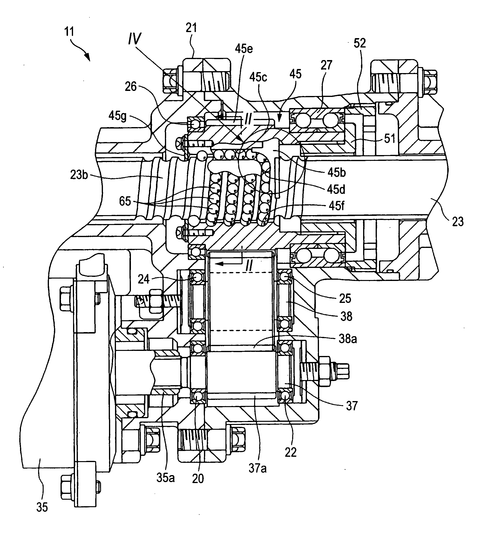
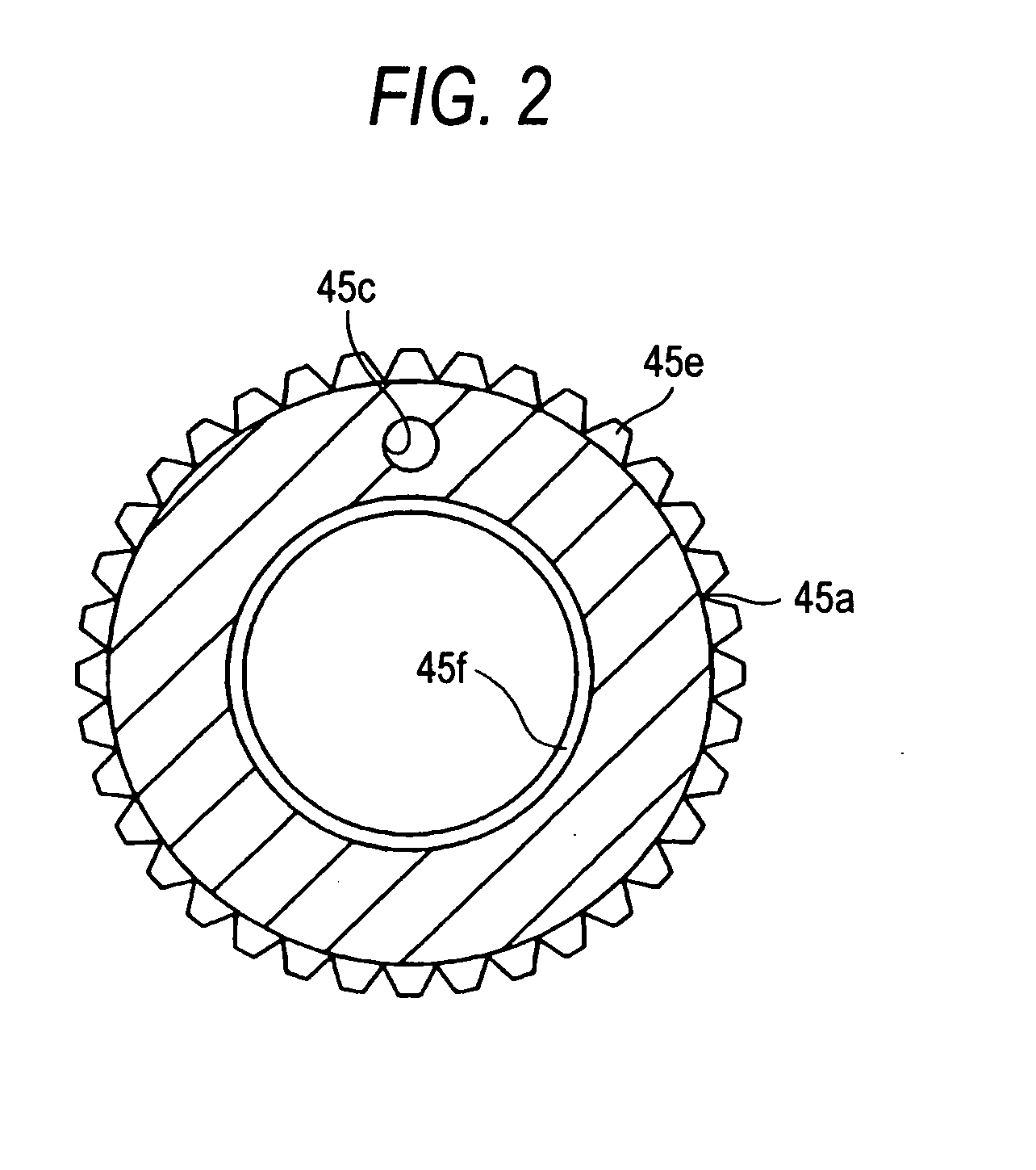
[0153]An embodiment of the present invention will now be described with reference to the drawings. FIG. 1 is a cross-sectional view of an important portion of an electric power steering apparatus of the FIG. 2 is a view in which a nut of FIG. 1 is cut along the line II-II, and is seen in a direction of arrows, but a screw shaft and balls are omitted. In FIG. 1, the electric power steering apparatus 11 includes a housing 21 fixed to a vehicle body which is not shown. A rack shaft 23 extends horizontally through the housing 21, and is supported so as to be moved in an axial direction. Although not shown, a pinion is formed at a lower end of an input shaft connected to a steering wheel, and is in mesh with rack teeth of the rack shaft 23, and the rack shaft 23 is moved left and right in the drawings by rotation of the input shaft. Opposite ends of the rack shaft 23 are connected to a tie rod (not shown) of a steering mechanism.
[0154]An electric motor 35 is mounted on the housing 21 in...
second embodiment
[0164]FIG. 3 is a cross-sectional view of an important portion of an electric power steering apparatus 111 of a In this embodiment, only those points different from the embodiment shown in FIGS. 1 and 2 will be described, and with respect to common constructions, identical reference numerals will be applied, and explanation thereof will be omitted.
[0165]In this embodiment, instead of omitting the intermediate shaft, there is provided a toothed belt 55 engaged with a gear portion 37a of a drive gear 37 and a driven gear portion 45e of a body 45. Therefore, when the drive gear portion 37a rotates together with an output shaft 35a of an electric motor 35, the driven gear portion 45e is rotated at a predetermined reduction ratio via the toothed belt 55. As a result, a nut 45 also rotates, and therefore power of the electric motor 35 can be transmitted to a screw shaft 23. Incidentally, a chain may be used instead of the toothed belt.
third embodiment
[0166]FIG. 6 is a cross-sectional view of an important portion of an electric power steering apparatus 211 of a FIG. 7 is an exploded view of a nut and a driven gear, and FIG. 8 is a view of the nut as seen in an axial direction, with deflectors removed therefrom.
[0167]In FIG. 6, the electric power steering apparatus 211 has a housing 121 fixed to a vehicle body not shown. The housing 121 is divided into three sections in FIG. 6, and comprises members 121A, 121B, 121C fastened together into a unitary form by bolts. A rack shaft 123 extends horizontally through the housing 121, and is supported so as to be moved in an axial direction. Although not shown, a pinion is formed at a lower end of an input shaft connected to a steering wheel, and is in mesh with rack teeth of the rack shaft 123, and the rack shaft 123 is moved left and right in the drawings by rotation of the input shaft. Opposite ends of the rack shaft 123 are connected to a tie rod (not shown) of a steering mechanism.
[01...
PUM
 Abstract
Description
Claims
Application Information
 - Generate Ideas
- Intellectual Property
- Life Sciences
- Materials
- Tech Scout
- Unparalleled Data Quality
- Higher Quality Content
- 60% Fewer Hallucinations
Browse by: Latest US Patents, China's latest patents, Technical Efficacy Thesaurus, Application Domain, Technology Topic, Popular Technical Reports.
© 2025 PatSnap. All rights reserved.Legal|Privacy policy|Modern Slavery Act Transparency Statement|Sitemap|About US| Contact US: help@patsnap.com