Wear resistant, heat resistant conveyor chain

a conveyor chain and wear-resistant technology, applied in the direction of conveyors, packaging, transportation and packaging, etc., can solve the problems of reducing the life of the chain, affecting the operation of the chain, and generating abnormal one-sided wear between the roller and the bush, so as to achieve the effect of ensuring the quiet environment of the chain operation, reducing wear and elongation, and reducing wear

Inactive Publication Date: 2009-12-03
TSUBAKIMOTO CHAIN CO
View PDF8 Cites 3 Cited by
  • Summary
  • Abstract
  • Description
  • Claims
  • Application Information

AI Technical Summary

Benefits of technology

[0008]Since the present invention has the following configurations in a wear resistant, heat resistant conveyor chain comprising a pair of right and left spaced inner plates, a bush press-fitted into bush holes in said inner plates, a heat resistant roller rotatably fitted onto the bush, a connecting pin rotatably inserted into said bush and a pair of right and left spaced outer plates, which connects said inner plates in a longitudinal direction of the chain by press-fitting both ends of said connecting pin into pin holes, the present invention has particularly advantageous effects.
[0009]Because the sleeve-shaped spacer protrudes beyond the end surfaces of the heat resistant roller toward the pair of right and left inner plates, the sliding contact between the roller end surfaces of the heat resistant roller and the inner side surfaces of the inner plate can be fully avoided. Thus, any metallic powder liable to be produced between the end surface of the heat resistant roller and an inner side surface of the inner plate is blocked, even under environment of a heat resistant operation, so that smooth sliding contact between an inner circumferential surface of the heat resistant roller and an outer circumferential surface of the bush can be maintained without generating one side wear therebetween, and, at the same time, chain wear elongation is significantly suppressed so that the life of the chain can be maintained for a long period of time. Further, the sliding contact noise between the inner circumferential surface of the heat resistant roller and the outer circumferential surface of the bush is reduced so that quiet environment of a chain operation can be ensured.
[0010]Further, when the sleeve-shaped spacer is integrally adhered to an inner circumferential surface side of a heat resistant roller, in addition to blocking the formation of any metallic powder, the invention avoids skewing, rocking or one-side positioning of the heat resistant roller in a chain width direction on an outer circumferential surface of the sleeve-shaped spacer during an operation of the chain. Thus, the snaking of the chain in the chain width direction is suppressed so that stable chain traveling can be realized.
[0011]Further, when the sleeve-shaped spacer comprises a pair of right and left flanged ring members, the flanges of the flanged ring members eliminate any sliding contact between an end surface of the heat resistant roller and an inner side surface of the inner plate and reliably positions the heat resistant roller on a flanged ring member so that skewing, rocking or one-side positioning of the heat resistant roller in the chain width direction can be blocked, and contact surface pressure of the sleeve-shaped spacer with respect to an inner side surface of the inner plate is reduced whereby abrasion loss of the flanged ring member itself is suppressed and a long insulation function between the end surface of the heat resistant roller and the inner side surface of the inner plate can be achieved.
[0012]Further, when a pair of right and left flanged ring members are each loosely fitted between the heat resistant roller and the bush, the assembling operation of the chain and the assembling / disassembling operation during any coupling / decoupling operation of the chain are easily performed and any difference in coefficients of thermal expansion between the heat resistant roller and the bush is accommodated so that smooth sliding contact can be maintained. Further, since the pair of right and left flanged ring members are rotated about the bush at a rotating speed slower than the heat resistant roller due to slip generated between the flanged ring member and the heat resistant roller, the sliding wear with respect to the inner side surface of the inner plate is even more reduced so that excellent endurance can be exhibited.
[0013]Any chain wear elongation due to one-side wear between an inner circumferential surface of a roller and an outer circumferential surface of a bush is significantly suppressed even under environment of a heat resistant operation so that the life of the chain is maintained for a long period of time, and sliding contact noise between the inner circumferential surface of the roller and the outer circumferential surface of the bush is reduced so that quiet chain operation is ensured.

Problems solved by technology

However, in the above-mentioned conveyor chain, a metallic wear powder produced due to sliding contact between an end surface of a roller and an inner side surface of an inner link plate enters between an inner circumferential surface of the roller and an outer circumferential surface of the bush, and such metallic wear powder functions as a polishing agent and generates abnormal one side wear between the roller and the bush.
As a result there were troublesome problems in handling of the chain in that a chain wear elongation is not only increased (to markedly decrease the life of the chain) but also the sliding contact sound during a chain operation is markedly increased.

Method used


Image

  • Wear resistant, heat resistant conveyor chain
  • Wear resistant, heat resistant conveyor chain
  • Wear resistant, heat resistant conveyor chain

Examples


Embodiment Construction

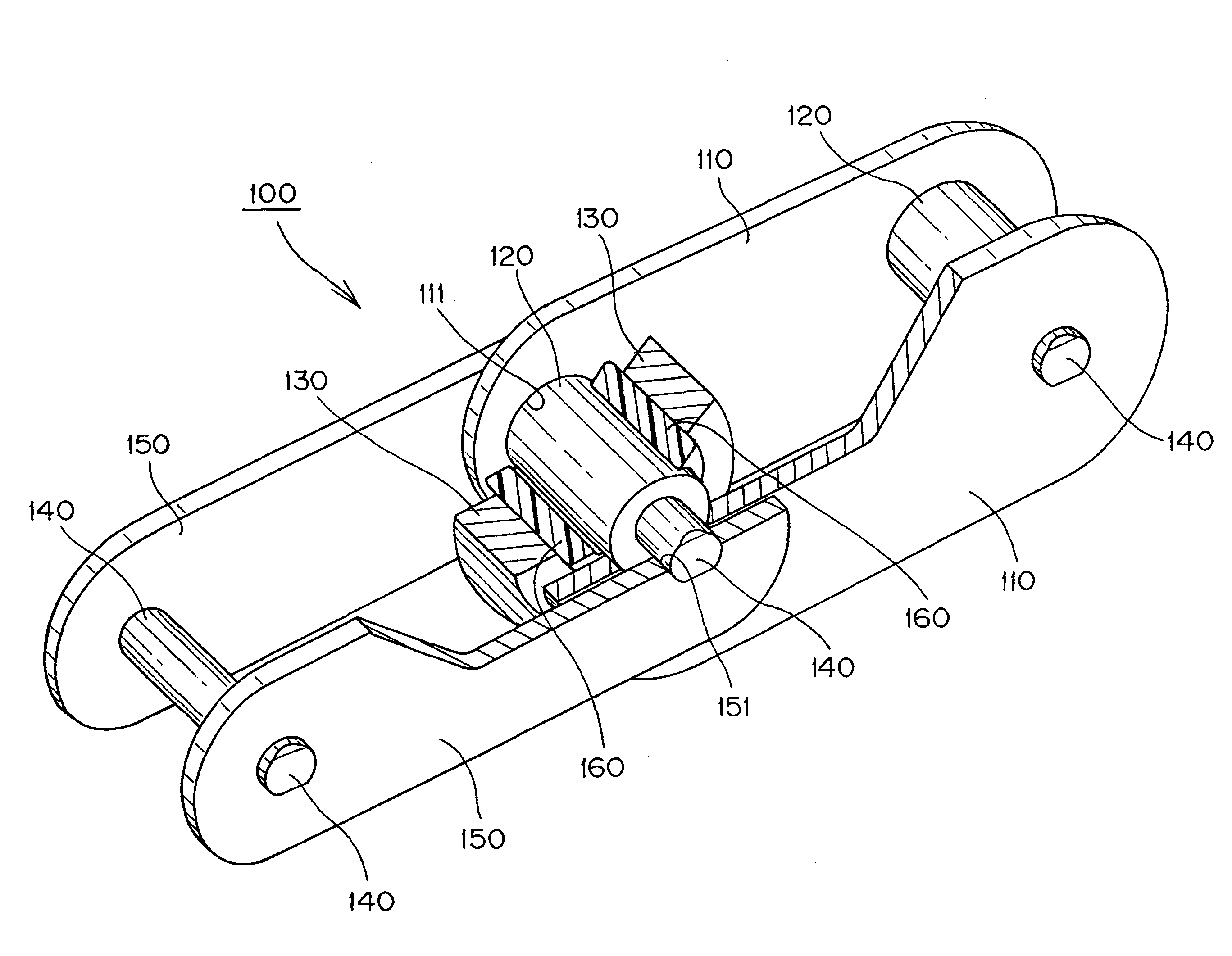
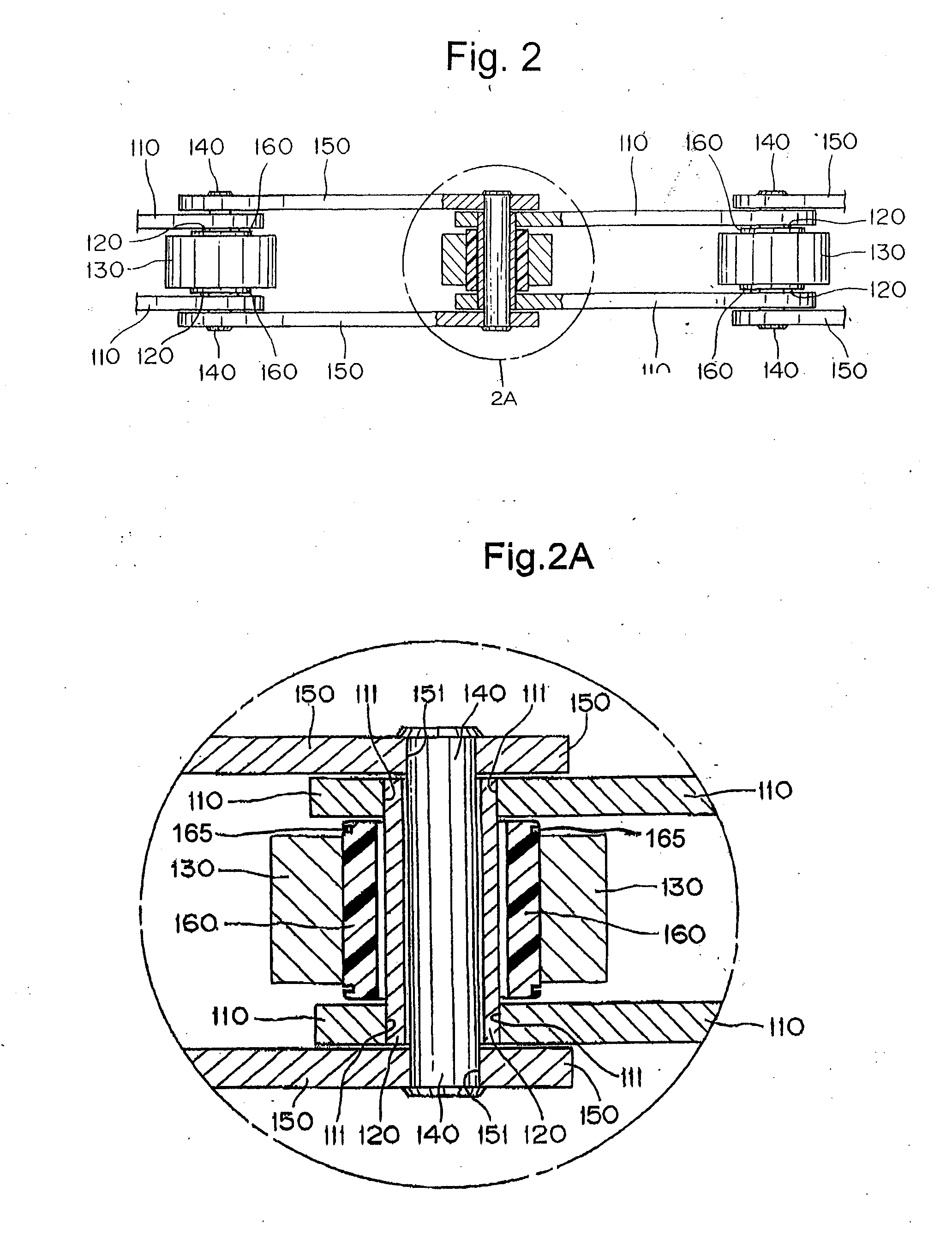
[0025]As shown in FIGS. 1 and 2, the first example of the present invention comprises a chain 100 having a series of links, each with a pair of right and left spaced inner plates 110, bushes 120 press-fitted into bush holes 111 in the inner plates 110, a heat resistant roller 130 rotatably fitted onto the bush 120. The links are interconnected by connecting pins 140 rotatably inserted into the bush 120 and a pair of right and left spaced outer plates 150 which interconnect the inner plates 110 of adjoining links in a longitudinal direction of the chain by press-fitting both ends of the connecting pins 140 into pin holes 151. The chain is preferably used while incorporated into a bread baking oven (not shown).

[0026]Preferably, the chain parts comprising the above-mentioned inner plates 110, the bush 120, the heat resistant roller 130, the connecting pin 140, and the outer plates 150 are all made of stainless steel having heat resistance. Therefore, even if the temperature in a bread ...


PUM


Abstract

A wear resistant, heat resistant conveyor chain comprising a series of links, each having a heat resistant roller rotatably fitted onto a bush between inner plates. The links are interconnected in the longitudinal direction of the chain by outer plates, and connecting pins rotatably inserted into the bush. A wear resistant, heat resistant sleeve-shaped spacer protrudes beyond the end surfaces of the heat resistant rollers toward the right and left inner plates to eliminate any sliding contact between the end surface of the heat resistant roller and the inner side surface of the inner plate.

Description

FIELD OF INVENTION[0001]The present invention relates to a wear resistant, heat resistant conveyor chain used in a conveying device, and more specifically it relates to a wear resistant, heat resistant conveyor chain used under environment of heat resistant operation of a bread baking oven or the like.BACKGROUND OF THE INVENTION[0002]As a conveyor chain used under severe use environment required for heat resistance and the like, a conveyor chain in which a number of link plates are continuously connected to each other through link pins and a roller is attached to said link pin through a bush, characterized in that said bush is composed of stainless steel and said roller is composed of at least a PEEK resin (polyetheretherketone resin) in at least an inner diameter portion, has been known (see, for example, Japanese Laid-Open Patent Publication No. He1. 6-227632 (see column 1, FIG. 3)).[0003]However, in the above-mentioned conveyor chain, a metallic wear powder produced due to slidin...

Claims


Application Information

Patent Timeline
Patent Type & Authority Applications(United States)
IPC IPC(8): B65G17/38
CPCB65G17/38B65G2207/48B65G2207/12
Inventor NAKAGAWA, TAKASHIISHIDA, HIROKIFUJIWARA, MAKOTONAKAMURA, RYUTAROKITAO, NOBUONAGATA, TATSUONAKATOU, SATOSHI
Owner TSUBAKIMOTO CHAIN CO
Why Eureka
Try Eureka