Pharmaceutical waste container system

a technology for pharmaceutical waste and container systems, applied in the direction of containers preventing decay, applications, refuse gathering, etc., can solve the problems of increasing the chance that injectable pharmaceutical liquid will end up in a local water supply environment, and the risk of hazardous consequences

Inactive Publication Date: 2009-12-03
HITSON TAMARA
View PDF33 Cites 14 Cited by
  • Summary
  • Abstract
  • Description
  • Claims
  • Application Information

AI Technical Summary

Benefits of technology

[0007]In yet other embodiments, a pharmaceutical waste disposal device comprises an upper portion adapted for receiving pharmaceutical waste and a lower portion adapted for collecting the pharmaceutical waste, the lower portion being selectively and removably engagable with the upper portion. The upper portion includes a housing surrounding an internal rotating wheel and a lid slideably engaged with the housing. Additionally, the rotating wheel includes collection areas adapted for collecting pharmaceutical waste placed in the upper portion. The lid includes a lower pivoting flap adapted for contacting and rotating the wheel upon closing the lid to transfer the pharmaceutical waste to the lower portion. Further, the rotating wheel is sized and positioned within the housing in a manner to substantially prevent access to the pharmaceutical waste collected in the lower portion.

Problems solved by technology

However, before medical needles are disposed of within the sharps containers, often the injectable pharmaceutical liquid within the syringe is discharged down a drain within the medical facility, joining the medical facility's wastewater and possibly traveling to a wastewater treatment site.
Unfortunately, wastewater treatment sites are often incapable of properly treating various types of pharmaceutical waste, thereby increasing the chance that the injectable pharmaceutical liquid will end up in a local water supply environment.
Similarly, medical personnel often dispose of solid pharmaceutical waste by rinsing the waste down a drain in the medical facility, resulting in the same hazardous implications described above with respect to liquid pharmaceutical waste.

Method used


Image

  • Pharmaceutical waste container system
  • Pharmaceutical waste container system
  • Pharmaceutical waste container system

Examples


Embodiment Construction

[0014]For the purposes of promoting an understanding of the principles of the disclosure, reference will now be made to the embodiment illustrated in the drawings and specific language will be used to describe the same. It will nevertheless be understood that no limitation of the scope of the disclosure is thereby intended, and alterations and modifications in the illustrated device, and further applications of the principles of the disclosure as illustrated therein are herein contemplated as would normally occur to one skilled in the art to which the disclosure relates.

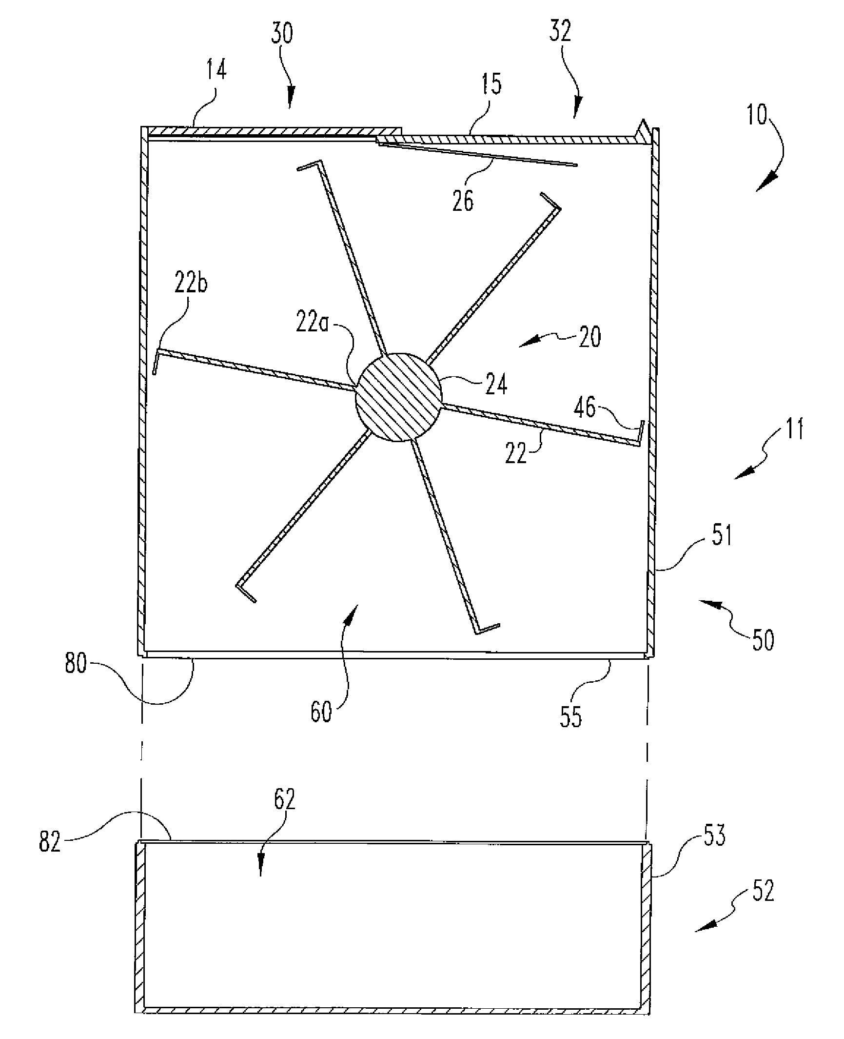
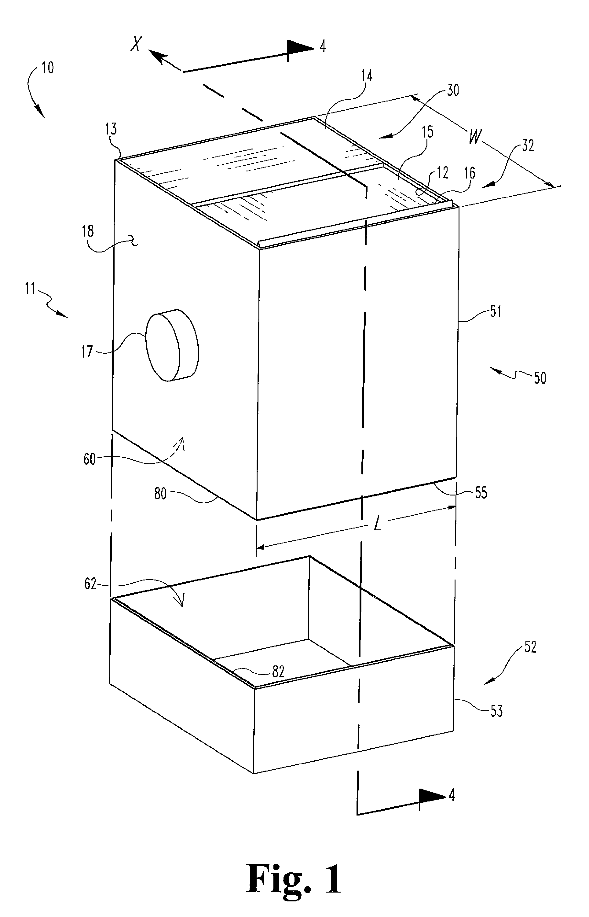
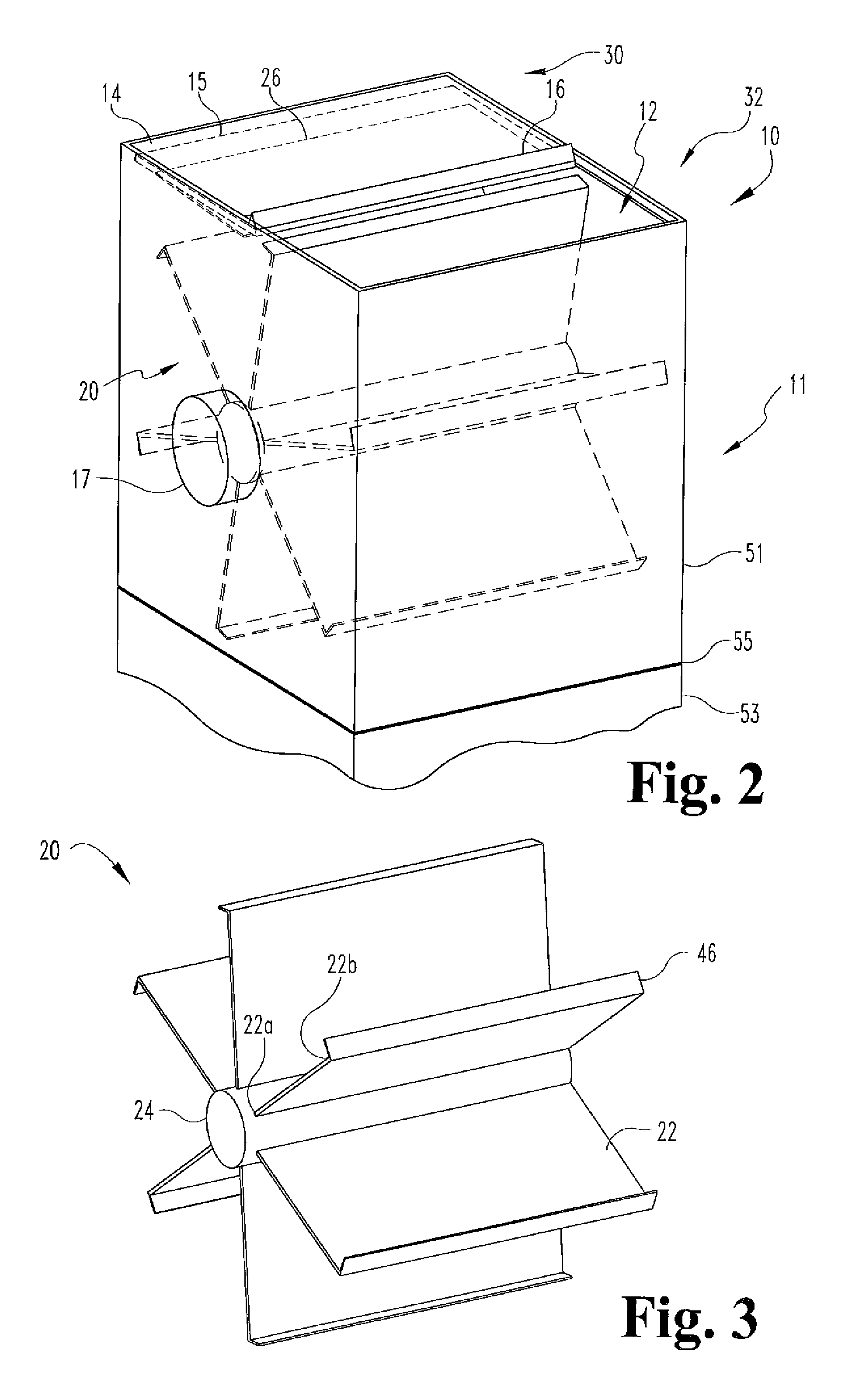
[0015]Referring generally to FIGS. 1 through 5B, components of a pharmaceutical waste container system are shown. More specifically, FIGS. 1 through 4A illustrate one embodiment of a solid waste container 10 and FIGS. 5A and 5B illustrate one embodiment of a liquid waste container 110. It is contemplated that containers 10 and 110 can be positioned together in a combined, collective and complete waste container syste...


PUM


Abstract

A pharmaceutical waste disposal device comprises an upper portion adapted for receiving pharmaceutical waste and a lower portion adapted for collecting the pharmaceutical waste, the lower portion being selectively and removably engagable with the upper portion. The upper portion includes a housing surrounding an internal rotating wheel and a lid slideably engaged with the housing. Additionally, the rotating wheel includes collection areas adapted for collecting pharmaceutical waste placed in the upper portion. The lid includes a lower pivoting flap adapted for contacting and rotating the wheel upon closing the lid to transfer the pharmaceutical waste to the lower portion. Further, the rotating wheel is sized and positioned within the housing in a manner to substantially prevent access to the pharmaceutical waste collected in the lower portion.

Description

CROSS-REFERENCE TO RELATED APPLICATIONS[0001]This application claims the benefit of U.S. Provisional Application No. 61 / 056,659, filed May 28, 2008, which is hereby incorporated by reference.FIELD OF DISCLOSURE[0002]The present disclosure relates to the field of waste handling containers and specifically to solid and liquid pharmaceutical waste containers.BACKGROUND OF THE DISCLOSURE[0003]In recent years, there has been an increasing focus on the safety and environmental impact of the disposal of hazardous waste materials, and specifically pharmaceutical waste. In many medical facilities such as hospitals and nursing homes, sharps containers are utilized for the disposal of medical needles. These containers collect the disposed medical needles and then the containers themselves may be collected by approved individuals and transferred to medical waste treatment sites. However, before medical needles are disposed of within the sharps containers, often the injectable pharmaceutical liq...

Claims


Application Information

Patent Timeline
IPC IPC(8): B65D81/00
CPCA61B19/0287A61B19/0288B65F1/10A61B2019/0213A61B2019/0209A61B50/36A61B50/362A61B2050/0056A61B2050/006
Inventor HITSON, TAMARA
Owner HITSON TAMARA
Why Eureka
Try Eureka