
Controlled release of additive compositions

a technology of additive compositions and compositions, applied in the direction of separation, separation process, dissolving, etc., can solve the problems of insoluble components of the present apparatus that may or may not be reused, and achieve the effect of high effective and convenient control of the releas

Inactive Publication Date: 2009-12-03
DOBER CHEMICAL CORPORATION
View PDF81 Cites 7 Cited by
  • Summary
  • Abstract
  • Description
  • Claims
  • Application Information

AI Technical Summary

Benefits of technology

[0006]New apparatus and methods for providing release, preferably sustained release, of additive compositions comprising a chemical additive component into a liquid composition have been discovered. The present apparatus and methods effectively provide for gradual, preferably sustained, and more preferably substantially controlled, release of additive compositions from the apparatus into liquid compositions, for example, aqueous liquid compositions; a liquid comprising water and at least one freezing point depressant, such as at least one glycol; substantially non-aqueous liquids; and the like. Advantageously, the additive composition is released only through a limited portion of the apparatus, for example, over a relatively prolonged period of time. The present apparatus and methods have been found to be highly effective and convenient in controlling the release of additive compositions into liquid compositions.
[0007]Many components of the apparatus of the invention, for example, other than the additive composition, are substantially insoluble in the liquid composition so that these components remain intact and do not dissolve into and / or otherwise detrimentally affect the liquid composition or the system in which the liquid composition is located or employed. In addition, the insoluble components of the present apparatus may or may not be reused after release of the additive composition contained therein. The present apparatus are easy and straightforward to manufacture cost effectively and can easily and effectively be used in a relatively wide variety of systems / applications with little or no modification to effectively control the release of the additive composition into the liquid composition and / or the quality of the liquid composition.
[0013]In one embodiment, the casing includes a further opening. A structure is provided which is operatively coupled to the further opening and operable to allow air to pass out of the hollow interior through the further opening and to substantially prevent a liquid composition from passing out of the hollow interior through the further opening. Such structure, for example and without limitation, selected from including an element, a membrane member, a valve and the like, facilitates effective contact between the additive composition in the casing and the liquid composition being treated. In one embodiment, the structure is advantageously effective to allow the liquid composition and additive composition to exit the hollow interior of the casing through the at least one opening, while substantially preventing such release through the further opening.
[0014]In a useful embodiment, the structure is effective to substantially prevent liquid composition in contact with the casing from entering the hollow interior through the further opening. The structure may include a removable plug which is removably fitted into the further opening. With the plug removed, liquid composition may be added to the hollow interior of the casing to pre-condition, e.g., pre-wet, the additive composition in the hollow interior prior to use of the container. Such pre-conditioning may facilitate the timely initial release of one or more additive components in the additive composition which are difficult to wet and, therefore, without such pre-conditioning, e.g., pre-wetting, are released into the liquid composition only after an unacceptably long period of time after the container is placed in use. During use of the container in treating a liquid composition, the plug may be reinserted into the further opening, for example, to substantially prevent the liquid composition and additive composition from leaving the hollow interior of the casing through the further opening.

Problems solved by technology

Advantageously, the additive composition is released only through a limited portion of the apparatus, for example, over a relatively prolonged period of time.
In addition, the insoluble components of the present apparatus may or may not be reused after release of the additive composition contained therein.

Method used


Image

  • Controlled release of additive compositions
  • Controlled release of additive compositions
  • Controlled release of additive compositions

Examples


example 1

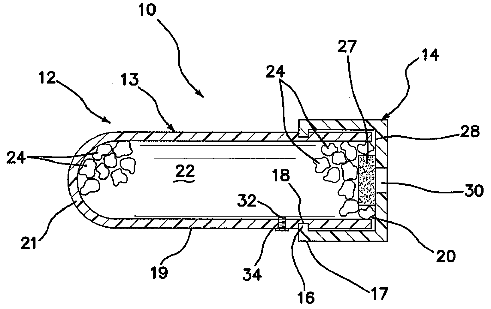
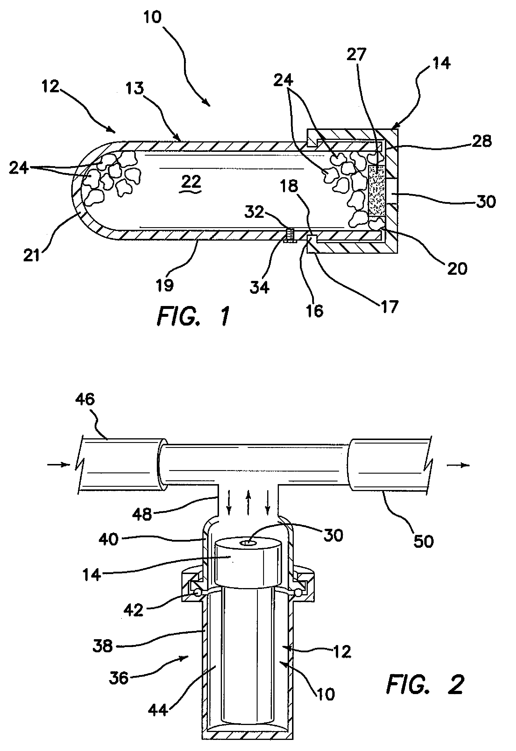
[0096]Referring now to FIG. 1, container 10 comprises a PVC casing 12 including a solid, open ended, generally cylindrically shaped casing body 13 and an end cap 14, which are fitted onto the casing body using a pair of pegs 16, inwardly extending from an end 17 of the cap 14, fitted into an annular groove 18 in the outer sidewall 19 of the casing body. The casing body 13 has an open end 20 and an opposing closed end 21. The casing 12 defines a hollow interior 22.

[0097]Provided within the hollow interior 22 are particles 24 containing an additive composition comprising a mixture of conventional corrosion inhibitors, scale inhibitors and defoamers, such as the composition sold by Fleetguard under the trademark DCA-2. The coolant composition to be treated using container 10 is an industrial aqueous liquid composition, for example, an aqueous-based liquid coolant used in a cooling tower.

[0098]A porous membrane 27 is adhered to the inner wall 28 of the end cap 14 and covers an opening 3...

example 2

[0106]As shown in FIG. 2, container 10 (as shown in FIG. 2) is positioned in vertical alignment with cylindrical housing 36 provided in a “bypass” configuration with a coolant system, for example, a cooling tower system. A representative diameter for the opening 30 in end cap 14 is 9 mm. As shown, housing 36 includes a housing body 38 and a housing top 40 which interlock to secure the container 10 within the housing 36. A housing O-ring seal 42 is provided between housing body 38 and housing top 40 to seal the interior space 44 of housing 36.

[0107]Coolant (liquid composition) flows from inlet line 46, enters and exits housing 36 through pipe segment 48, and exits via exit line 50. While inside housing 36, coolant passes in and out of opening or orifice 30, wetting membrane 27 and causing the release, for example, through diffusion, of additive composition from the particles 24 in casing 12 into the coolant. Generally, the liquid coolant flows into the inlet line 46 by the action of ...

example 3

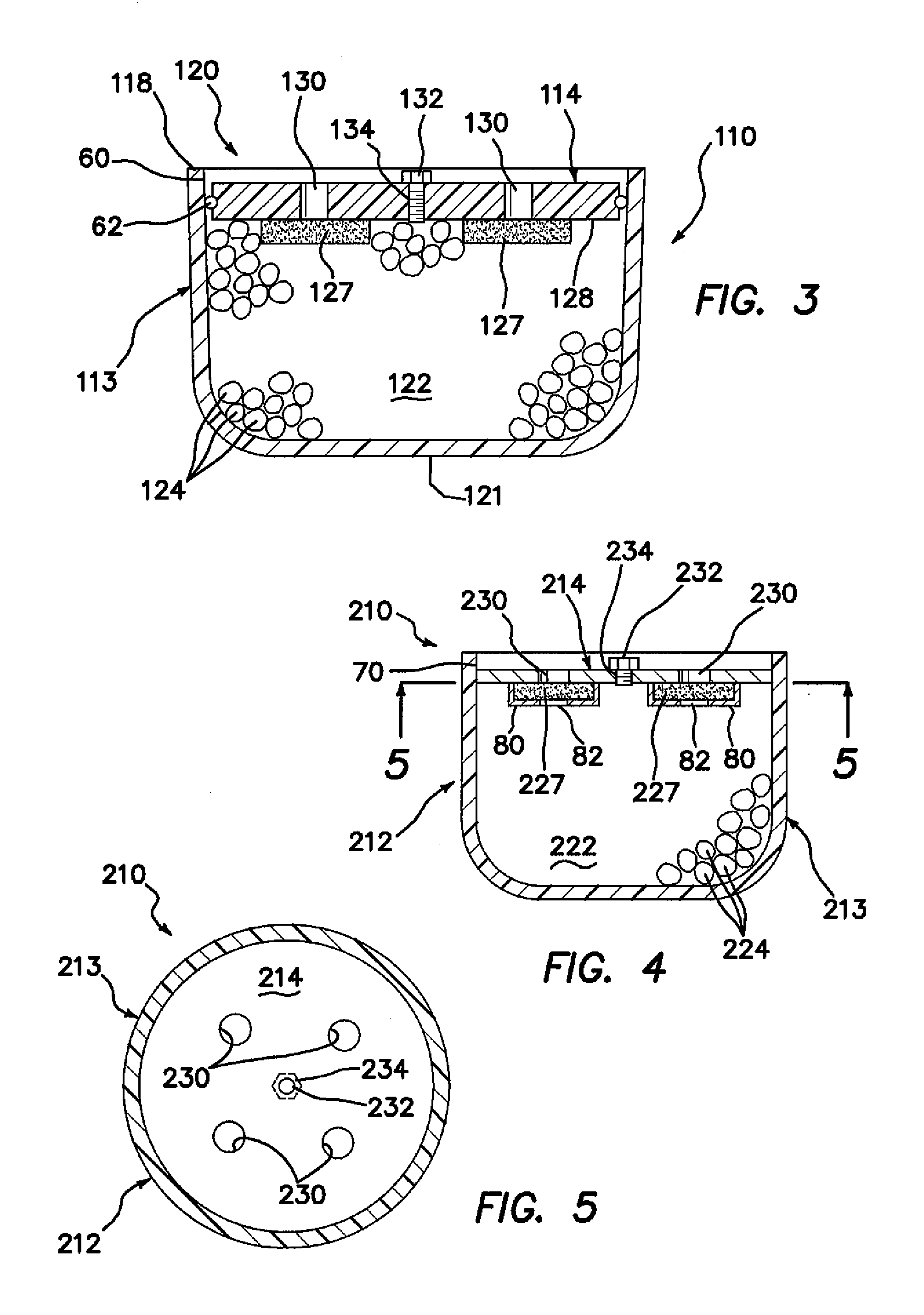
[0109]Turning now to FIG. 3, an additional container 110 of the present invention is shown. Except as expressly described herein, additional container 110 is structured and functions substantially similarly to container 10.

[0110]The container 110 generally comprises a bowl-shaped, liquid-impermeable casing body 113 having a hollow interior 122 filled with particles 124 of an additive composition, for example, as described in Example 1. The casing body 113 has a relatively wide open top end 120 which is, for example and without limitation, circular in shape, and an opposing closed end 121. The container 110 further comprises a cap member 114 disposed across, and preferably substantially completely covering, the open end 120.

[0111]The container 110 is useful in a coolant (liquid composition) line or a coolant sump, for example, of a cooling tower system (not shown). For example, container 110 may be placed in the coolant line, for example, in a manner analogous to that shown in FIG. 2...


PUM

PropertyMeasurementUnit
lengthaaaaaaaaaa
lengthaaaaaaaaaa
depthaaaaaaaaaa

Abstract

A container for releasing an additive composition into a liquid composition includes a liquid impermeable casing separate and apart from an internal combustion engine filter housing, and having a hollow interior, and at least one opening and a further opening into the hollow interior. The container further includes a structure operatively coupled to the further opening and operable to allow air to pass out of the hollow interior through the further opening and to substantially prevent a liquid composition from passing out of the hollow interior through the further opening. An additive composition is located in the hollow interior. At least one liquid permeable element, for example, a membrane member, is provided at or near the least one opening in the casing and is effective to provide for release of additive composition into the liquid composition. Methods of releasing additive compositions into liquid compositions are also provided.

Description

FIELD OF THE INVENTION [0001]The present invention relates to devices and methods for providing additive compositions comprising a chemical additive component to liquid compositions, such as industrial liquid compositions in cooling systems, for example, but not limited to, open circulating cooling or coolant systems, such as cooling towers and the like, humidification systems, recirculated spray water systems, fire quench tanks, fuel storage tanks, and the like.BACKGROUND OF THE INVENTION [0002]Liquids in various systems are plagued by the buildup of scale and / or corrosion and / or one or more other contaminant materials often due to thermal and / or otherwise caused breakdown of dissolved components and assault of dissolved electrolytes on surfaces, for example, metal surfaces, of the system and / or one or more other environmental conditions. In an effort to mitigate this buildup / contamination, various chemical additives typically are added periodically to the such systems, e.g., whene...

Claims


Application Information

Patent Timeline
Patent Type & Authority Applications(United States)
IPC IPC(8): C02F1/20C02F1/68C02F103/18
CPCC02F1/20C02F1/686C02F1/688B01F1/0027C02F2303/08C02F2303/12B01F5/0496C02F5/00C23F11/00B01F21/22B01F25/316
Inventor KELLY, DENNIS R.LITTLE, DAVID ALANSUNDARAM, MAGESH
Owner DOBER CHEMICAL CORPORATION
Learn More