Bracket and method for supporting a cubicle wall on a movable wall having horizontal mounting channels
Inactive Publication Date: 2009-12-03
CLINE JONATHAN
6 Cites 10 Cited by
AI-Extracted Technical Summary
Problems solved by technology
Unfortunately, a vertical wall strip system limits the placement of such hanging components at pre-existing vertical points along the movable wall where a vertical wall strip has been attached to the movable wall.
The placement of the vertical wall strips is determined during initial design of the interior space limiting the furniture and component shelf-life because their size becomes an issue.
Until this development, movable walls did not have the horizontal support available to support hanging components.
While a movable horizontal wall system, such as that described in Gosling et al., offers distinct advantages for movable wall systems, its use has generally been limited to furniture or other hanging components with the L-shaped hook that can engage with the horizontal stringers.
For those hanging components conventionally supported ...
Abstract
A bracket and method for supporting a cubicle wall on a movable wall having at least one horizontal mounting channel. The bracket has a lower bracket member and at least an upper bracket member that attaches to a movable wall module. A cubicle wall start is then coupled thereto. If a higher cubicle is needed, the bracket will have at least one intermediate bracket member to increase the overall length of the bracket.
Application Domain
Candle holdersLighting support devices +14
Technology Topic
Structural engineering
Image
Examples
- Experimental program(1)
Example
[0042]The novel features believed characteristic of the invention are set forth in the appended claims. The invention will best be understood by reference to the following detailed description of illustrated embodiments when read in conjunction with the accompanying drawings, wherein like reference numerals and symbols represent like elements.
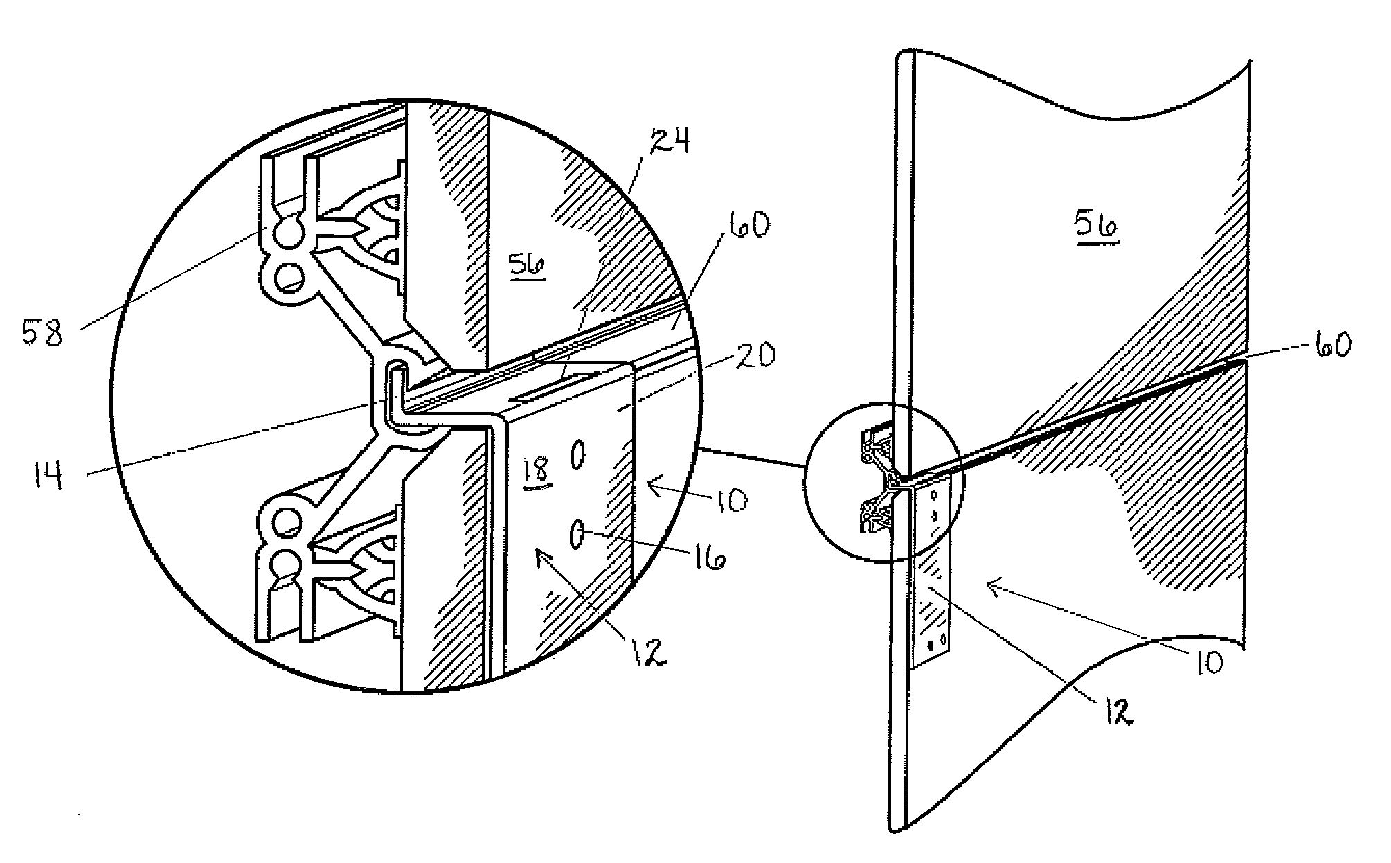
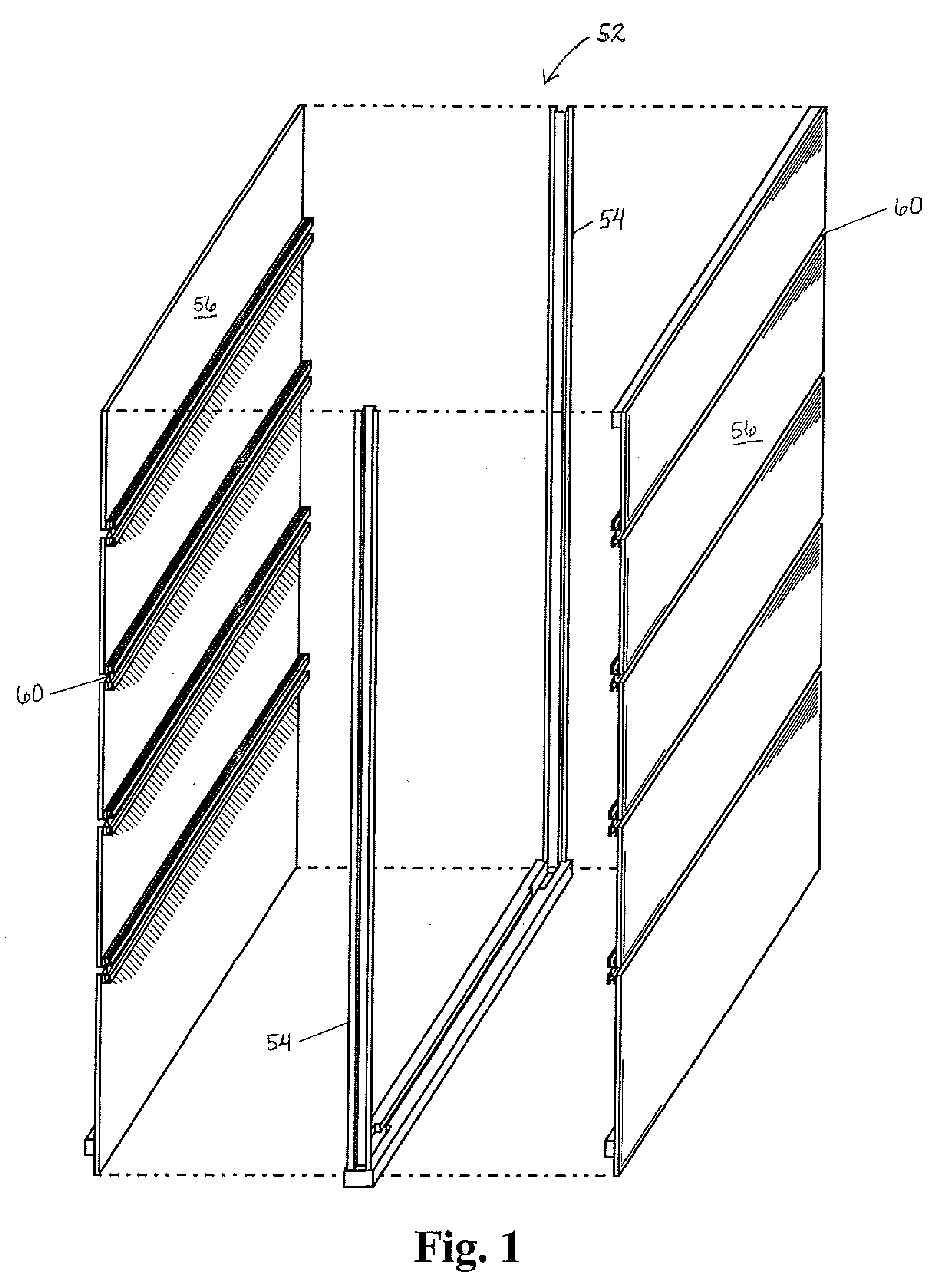
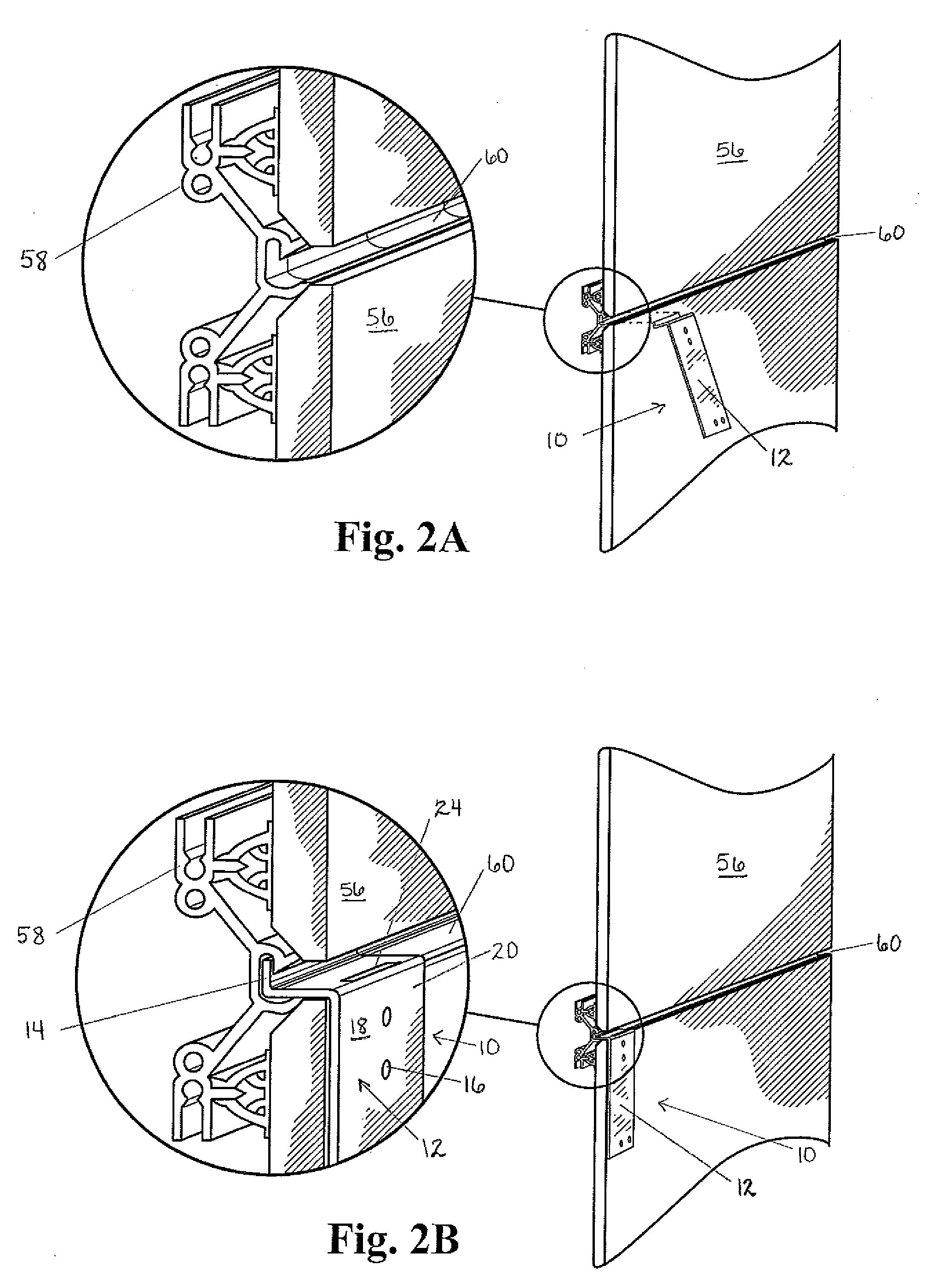
[0043]FIGS. 1-15 together show a bracket, hereinafter bracket 10, in accordance with the present invention. The bracket 10 permits modular cubicle walls 48 (6B-6D) to be removably attached to movable walls having at least one horizontal mounting channel 60. As known in the prior art, the movable walls may be comprised of at least one wall module 52 or panel such as that shown in FIG. 1 herein. Each wall module 52 generally comprises a pair of vertical end frames 54 that will be spaced apart by the desired width of each wall module 52. The wall modules 52 may be clad with wall tile 56 using a tile clip assembly 58 (see FIGS. 2A-2C) and can be one or two-sided with a finished wall surface on both sides or on one side only. Tiles 56 can be made of wood, plastic, metal fabric glass or other material, and the end frames 54 may be interconnected by a plurality of horizontal mounting channels 60.
[0044]A component bearing wall 30 or modular wall panel 16 may have four horizontal mounting channels 60 as shown in FIG. 1, although more or less horizontal mounting channels 60 may be used. The placement of the horizontal mounting channels 60 depends on the furniture configuration. While a particular configuration of a movable wall/movable wall module 52 has been described and shown, it is to be appreciated that the bracket 10 may be used with movable walls and movable wall modules 52 having other configurations.
[0045]The bracket 10 comprises a lower bracket member 12 and an upper bracket member 30. The lower bracket member 12 has an upper latch portion 14 and a lower planar portion 18. In one embodiment, the upper latch portion 14 of the lower bracket member 12 is an L-shaped flange with rearwardly and upwardly extending portions; wherein the rearwardly extending portion is parallel to the floor and the upwardly extending portion is perpendicular to the floor. The upper latch portion 14 is inserted into the horizontal mounting channel 60 and engages the tile clip assembly 58. It should be clearly understood that the upper latch portion 14 may have an alternate shape, as long as it will securely engage the tile clip assembly 58.
[0046]The lower planar portion 18 of the lower bracket member 12, according to one embodiment, may be rectangular. It should be clearly understood that substantial benefit may be derived from the lower planar portion 18 having any suitable shape. When the upper latch portion 14 is engaged with the tile clip assembly 58, a rear side of the lower planar portion 18 will rest flat against the wall module 52. The lower planar portion 18 will thus be perpendicular to the floor.
[0047]As shown in FIG. 2B, 4C and 4D, there is a void 24 in a top end of the lower bracket member 12. Where the upper latch portion 14 of the lower bracket member 12 is an L-shaped flange, the void 24 will be formed in the rearwardly extending portion of the L-shaped flange. The void 24 will be formed proximate the meeting point of the rearwardly extending portion and the lower planar portion 18 so that the void 24 is positioned anterior to the front surface of the wall module 52. In the embodiment shown in FIGS. 2A-6D, the void 24 may be a slot 24a that is rectangular with four sides (see FIGS. 2B, 4C, and 4D). In another embodiment shown in FIGS. 7-15, the void 24 may be a recess 24b (see FIG. 13).
[0048]The upper bracket member 30 has an upper planar portion 32 which, according to one embodiment, may be rectangular. It should be clearly understood that substantial benefit may be derived from the upper planar portion 32 having any suitable shape. The upper bracket member 30 also has a lower tab portion 36. As shown in FIGS. 2C, 5A, 5B, and 5C, the lower tab portion 36 is sized to be inserted into the slot 24a in the top end of the lower bracket member 12. When the lower tab portion 36 is inserted into the slot 24a, a rear side of the upper bracket member 30 will rest flat against the wall module 52; thus being perpendicular to the floor.
[0049]According to another embodiment, shown in FIGS. 7-15, the bracket 10 may also have an intermediate bracket member 40. The use of an intermediate bracket member 40 will increase the size of the bracket 10 as a whole so that it may be used to mount a cubicle wall 48 of greater height. The intermediate-bracket member 40 will have an upper latch portion 42 and a lower planar portion 46. Similar to the upper latch portion 14 of the lower bracket member 12, the upper latch portion 42 of the intermediate bracket member 40 may be an L-shaped flange with rearwardly and upwardly extending portions; wherein the rearwardly extending portion is parallel to the floor and the upwardly extending portion is perpendicular to the floor. Also in similar fashion, the upper latch portion 42 is inserted into a horizontal mounting channel 60 above the horizontal mounting channel 60 that is engaged by the upper latch portion 14 of the lower bracket member 12 and engages the tile clip assembly 58.
[0050]As shown in FIG. 12, there is a void 24 in a top end of the intermediate bracket member 12. It is similar to the slot 24a formed in the top end of the lower bracket member 12 of the embodiment shown in FIGS. 2A-6D. In other words, where the upper latch portion 42 of the intermediate bracket member 40 is an L-shaped flange, the void 24 will be formed in the rearwardly extending portion of the L-shaped flange. The void 24 will be formed proximate the meeting point of the rearwardly extending portion and the lower planar portion 46 so that the void 24 is positioned anterior to the front surface of the wall module 52.
[0051]The intermediate bracket member 40 also has a lower tab portion 47. As shown in FIG. 7A, 14, and 15, the lower tab portion 47 is sized to be inserted into the recess 24b in the top end of the lower bracket member 12. When the lower tab portion 47 is inserted into the recess 24b, a rear side of the intermediate bracket member 40 will rest flat against the wall module 52; thus being perpendicular to the floor. While in this embodiment, the void 24 in the lower bracket member 12 is shown as being a recess 24b, it should be clearly understood that substantial benefit may still be derived if the void 24 in this embodiment is a slot 24a.
[0052]In the embodiment shown in FIGS. 2A-6D, the lower planar portion 36 of the lower bracket member 12 has at least one opening 16 that aligns with at least one opening 16 in the lower tab portion 36 of the upper bracket member 30 when the lower tab portion 36 is inserted into the slot 24a in the top end of lower bracket member 12. As shown in FIGS. 5A-5C, these openings 16 are located in a top area 20 of the lower planar portion 18 of the lower bracket member 12. When the openings 16 in the top area 20 of the lower planar portion 18 of the lower bracket member 12 are aligned with the openings 16 in the lower tab portion 36 of the upper bracket member 30, a fastener 28 may be inserted through the openings 16. This will removably secure the lower bracket member 12 and the upper bracket member 30 together and will also secure the entire bracket 10 to the wall module 52 (see FIG. 2C).
[0053]In the embodiment shown in FIGS. 7-15, at least one opening 16 in the top area 20 of the lower planar portion 18 of the lower bracket member 12 aligns with at least one opening 16 in the lower tab portion 47 of the intermediate bracket member 40 when the lower tab portion 47 of the intermediate bracket member is inserted into the recess 24b in the top end of the lower bracket member 12. The intermediate bracket member 40 also has at least one opening 16 in its lower planar portion 46 that aligns with the opening 16 in the lower tab portion 36 of the upper bracket member 30 when the lower tab portion 36 of the upper bracket member 30 is inserted into the slot 24a in the top end of the intermediate bracket member 40. When the opening 16 in the top area 20 of the lower planar portion 18 of the lower bracket member 12 is aligned with the opening 16 in the lower tab portion 47 of the intermediate bracket member 40 and when the opening 16 in the lower planar portion 46 of the intermediate bracket member 40 is aligned with the opening 16 in the lower tab portion 36 of the upper bracket member 30, a fastener 28 may be inserted through the openings 16. This will removably secure the lower bracket member 12 to the intermediate bracket member 40 and secure the intermediate bracket member 40 to the upper bracket member 30. It will also secure the entire bracket 10 to the wall module 52.
[0054]The openings 16 may be punched, drilled, or otherwise formed in the bracket 10. Though not required, the openings 16 may also be pre-threaded to receive a threaded fastener such as a screw (see FIG. 6A). For example, in a preferred embodiment, pre-threaded PEM® nuts 54 may be pressure or snap fitted into the bracket openings 20 and the bracket openings with PEM® nuts are collectively referred to herein as “pre-threaded PEM® nut openings.” While the use of PEM® nut openings and machine screws are described, it is to be appreciated that other types of threaded openings and fasteners may be used within the confines of the invention. Furthermore, while the openings 16 in the lower tab portion 36 of the upper bracket member 30, the lower tab portion 47 of the intermediate bracket member 40, the top area 20 of the lower planar portion 18 of the lower bracket member 12, and the lower planar portion 46 of the intermediate bracket member 12 are shown as being two vertically aligned openings 16, it should be clearly understood that any suitable configuration and number of openings 16 may be used.
[0055]In a preferred embodiment as shown in FIGS. 3A, 4B, 8, and 10, there is at least one opening 16 in a top area 34 of the upper planar portion 32 of the upper bracket member 30. There is also at least one opening 16 in a bottom area 22 of the lower planar portion 13 of the lower bracket member 12. As shown in FIGS. 6A and 6B, these openings 16 will align with corresponding upper and lower openings 26 in a cubicle wall start 50. Fasteners 28 may be inserted through the openings 16, thus securing the cubicle wall start 50 to the bracket 10 and to the wall module 52. The spacing and number of openings 16 may vary depending on component configuration.
Statement of Operation
[0056]In the method of the invention, the upper latch portion 14 of the lower bracket member 12 (and similarly the upper latch portion 42 of the intermediate bracket member 40) may be received in and engage a horizontal mounting channel 60 as shown in FIGS. 2B and 2C. The substantially L-shaped flange may be inserted into the horizontal mounting channel 60 with the upwardly extending portion of the substantially L-shaped flange behind a top front edge of the horizontal mounting channel 60. The lower bracket member 12 is then swung downwardly toward the wall tile 56 until the rearwardly extending portion of the substantially L-shaped flange is seated over the lower bottom edge of the horizontal mounting channel 60. At this point, the lower bracket member 12 (or intermediate bracket member 40) is now engaged with the horizontal mounting channel 60 and may be slid horizontally anywhere along the length of the channel 60 to any position. The engaged lower bracket member 12 (or intermediate bracket member 40) hangs from the horizontal mounting channel 60 substantially flat against the wall tiles 56 of one or more modular wall panels 52 whereby the lower planar portion 18 of the lower bracket member 12 (or lower planar portion 46 of the intermediate bracket member 40) is disposed substantially perpendicular to the floor.
[0057]The bracket 10 may then be assembled by inserting the lower tab portion 36 of the upper bracket member 30 into the slot 24a in the lower bracket member 12, aligning the openings 12 of the lower bracket member 12 with the upper bracket member 30 and securing them to the wall module 52 with a fastener 28. If a larger bracket 10 is desired, then the lower tab portion 47 of the intermediate bracket member 40 will be inserted into the recess 24b in the lower bracket member 12 and the lower tab portion 36 of the upper bracket member 30 will be inserted into the slot 24a in the top end of the intermediate bracket member 40. The openings 12 of the lower bracket member 12, the intermediate bracket member 30, and the upper bracket member 30 will be properly aligned and the bracket will be secured to the wall module 52 with fasteners 28 through the openings 12. A cubicle wall start 50 will then be coupled to the bracket 10 with standard attachment hardware. A cubicle wall 48 may then be coupled to the cubicle wall start 50 and other furniture components (such as a tabletop 62 shown in FIG. 6D) may be added on.
[0058]For reconfiguring the space, the cubicle wall 48 and attachment hardware may be removed from the cubicle wall start 50 and wall module 52 in the conventional manner. The fasteners 28 may be removed from the aligned bracket 10 and openings 12 to unfasten the wall start 50 from the respective bracket(s) 10. To remove the bracket 10 from the horizontal mounting channel 60, the bracket 10 may be tilted upwardly and rotated so that the substantially L-shaped flange may be withdrawn from the horizontal mounting channel 60.
[0059]From the foregoing, it is to be appreciated that the bracket 10 and method permit support of modular cubicle walls 48 on movable walls having horizontal mounting channels 60 substantially eliminating the need for modification of the movable wall, cubicle wall or wall start, or attachment hardware.
[0060]While the invention has been particularly shown and S described with reference to preferred embodiments thereof, it will be understood by those skilled in the art that the foregoing and other changes in form and details may be made therein without departing from the spirit and scope of the invention.
PUM


Description & Claims & Application Information
We can also present the details of the Description, Claims and Application information to help users get a comprehensive understanding of the technical details of the patent, such as background art, summary of invention, brief description of drawings, description of embodiments, and other original content. On the other hand, users can also determine the specific scope of protection of the technology through the list of claims; as well as understand the changes in the life cycle of the technology with the presentation of the patent timeline. Login to view more.