Image sensor, image reading device and production method of image sensor

a technology of image reading and image sensor, which is applied in the direction of solid-state devices, instruments, material analysis, etc., to achieve the effect of reducing the warp of image sensors

Inactive Publication Date: 2009-12-03
NIPPON SHEET GLASS CO LTD
View PDF0 Cites 43 Cited by
  • Summary
  • Abstract
  • Description
  • Claims
  • Application Information

AI Technical Summary

Benefits of technology

[0009]In recent years, an image reading apparatus which enables reading of an original of the A3 or more size of the original has been requested. Similarly, an image sensor for the A3 or more size of the original has been requested. For the

Problems solved by technology

For the image sensor reading the A3 or more size of the original, there is a problem in the prior art that the more rigid ma

Method used


Image

  • Image sensor, image reading device and production method of image sensor
  • Image sensor, image reading device and production method of image sensor
  • Image sensor, image reading device and production method of image sensor

Examples


first embodiment

A First Embodiment

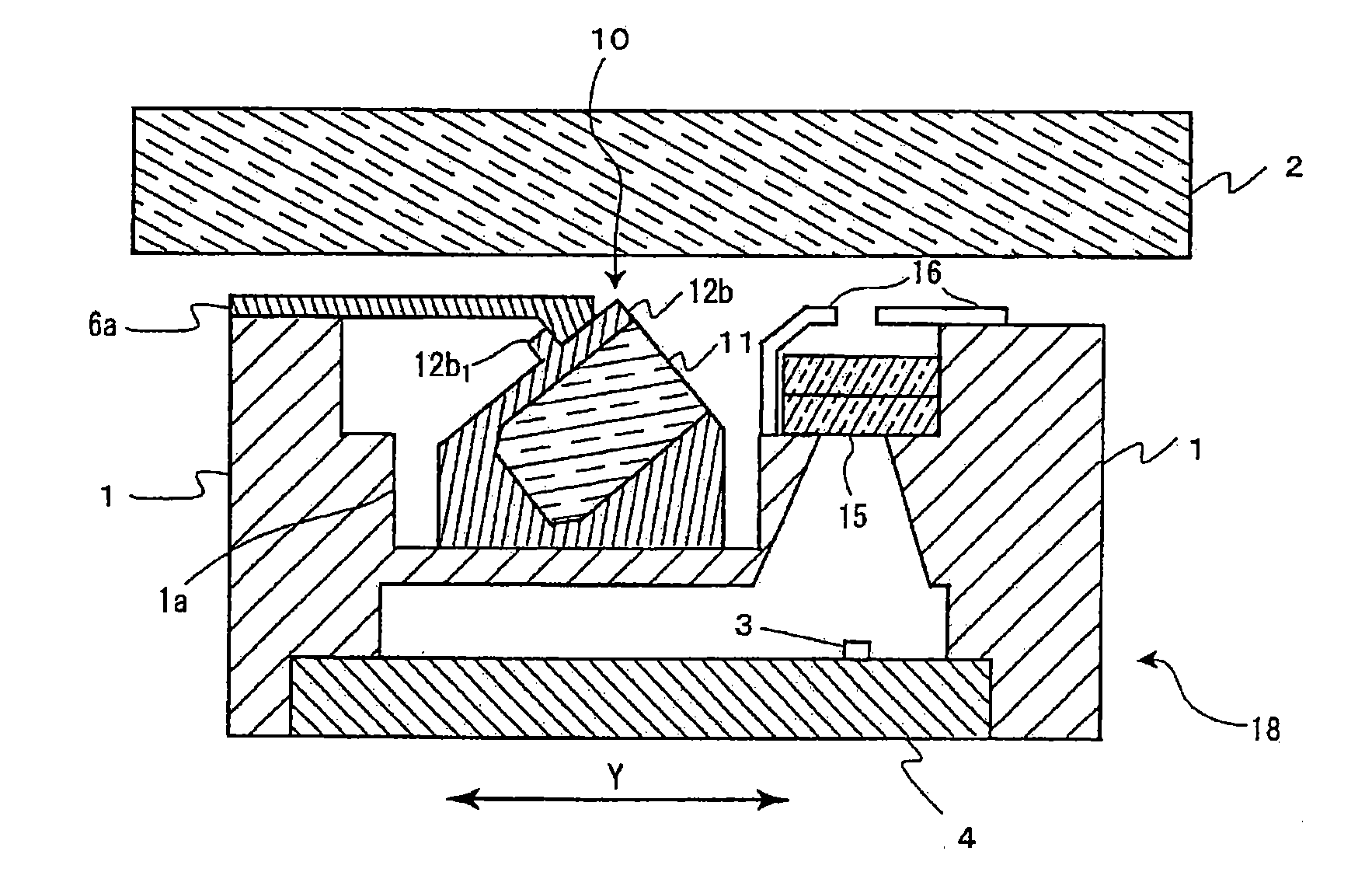
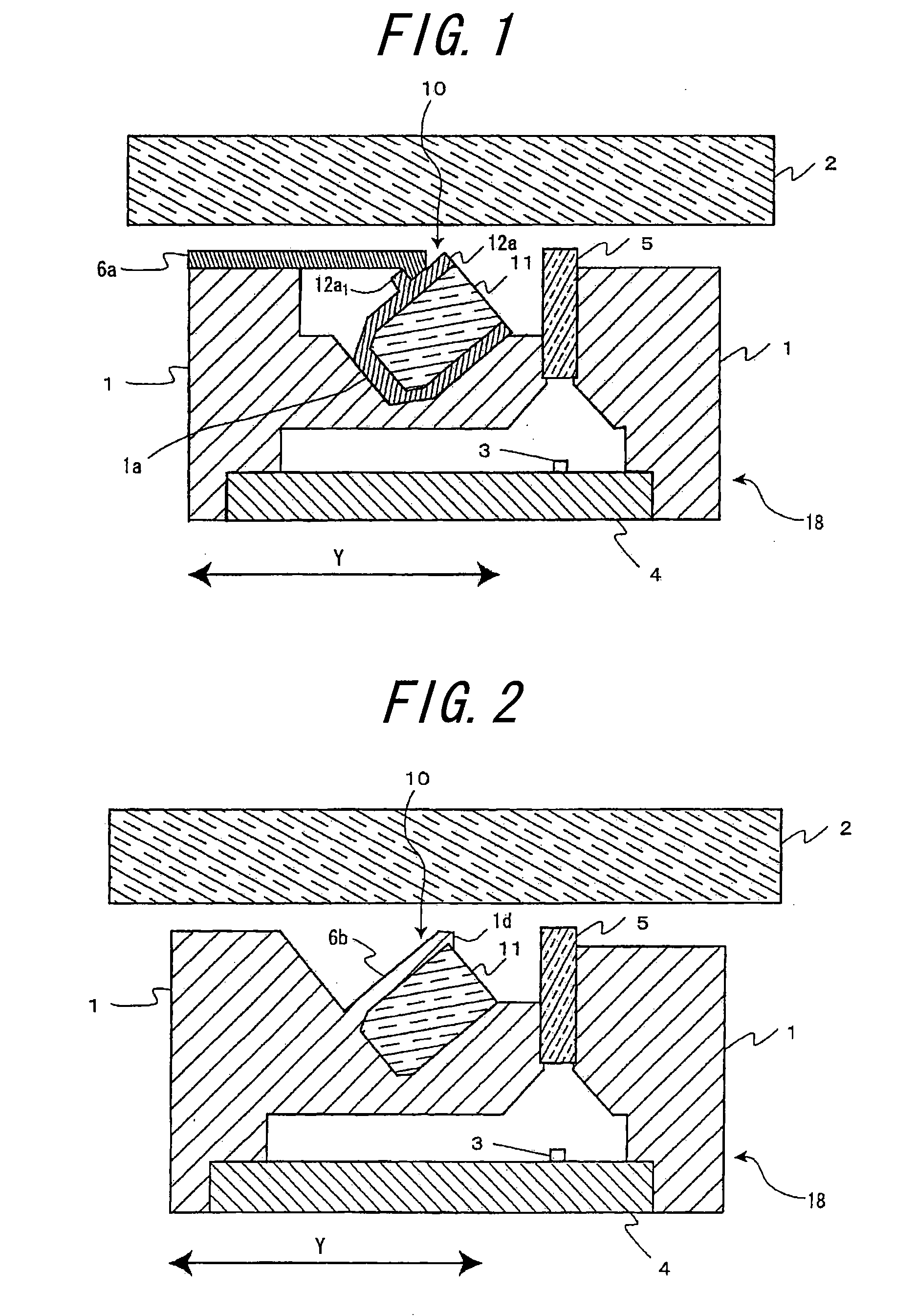
[0041]FIG. 1 is a cross-sectional view of an image sensor of a first embodiment in accordance with the present invention. An image sensor 18 comprises a frame 1, a lens array 5, a linear illuminating device 10, and a sensor substrate 4 provided with a light-receiving element array 3. The lens array 5, the linear illuminating device 10, and the sensor substrate 4 provided with the light-receiving element array 3 are contained into the frame 1.

[0042]The linear illuminating device 10 comprises a light guide 11, a case 12a, and light-emitting elements (not shown). In general, the light-emitting elements, which may include one or more light-emitting elements (for example, LED), may be arranged in one end or both ends of the linear illuminating device 10. The light irradiated from the light-emitting elements is irradiated from the irradiation side surface of the light guide 11, repeating the reflection within light guide 11. High reflection efficiency in the light guide ...

second embodiment

A Second Embodiment

[0049]Since a cross-sectional view of an image sensor in a second embodiment is similar to FIG. 1 described in the first embodiment, the detailed description is omitted.

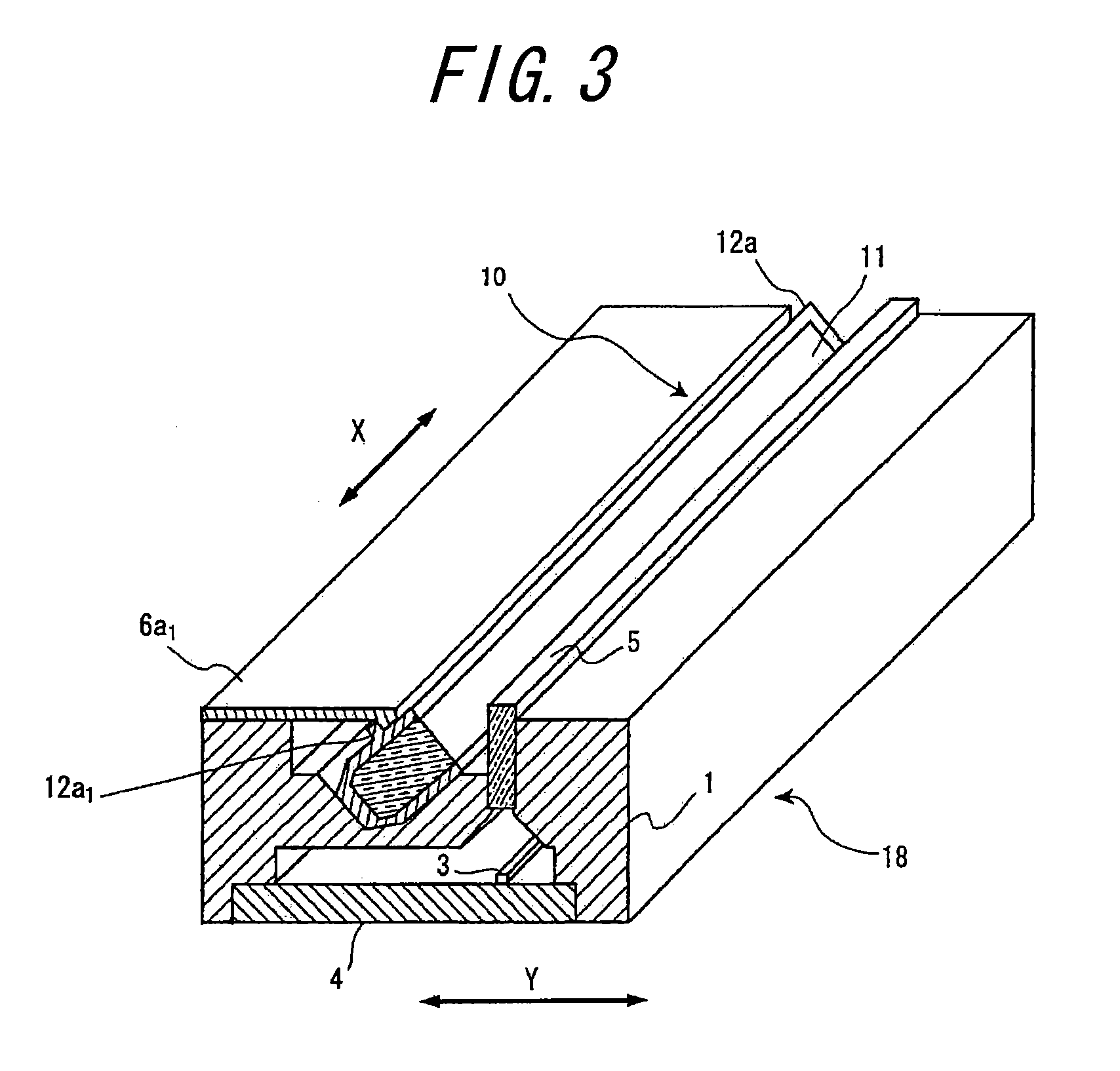
[0050]FIG. 4 is a perspective cross-sectional view of an image sensor of a second embodiment in accordance with the present invention. In the second embodiment, each of resilient retaining materials 6a2 shown in FIG. 4 has a function similar to the resilient retaining material 6a shown in FIG. 1. In this embodiment, the convex portion 12a1 in the side of the case 12a is formed over the entire length of the longitudinal direction in the case 12a. On the other hand, each of the resilient retaining materials 6a2 has been arranged in three places of the center and both ends of the longitudinal direction (i.e. the main-scanning direction indicated by an arrow X shown in FIG. 4) in the linear illuminating device 10. Therefore, the plurality of the resilient retaining materials 6a may be formed at optiona...

third embodiment

A Third Embodiment

[0051]FIG. 2 is a cross-sectional view of an image sensor of a third embodiment in accordance with the present invention. In FIG. 2, the frame 1 and a resilient retaining portion 6b are of integrated molding. This image sensor structure is similar to the first embodiment or the second embodiment, excluding the structure of an linear illuminating device 10, as well as a frame 1 and the resilient retaining portion 6b formed by integrated molding. Therefore, only the features of this embodiment are described.

[0052]In this embodiment, the resilient retaining portion 6b also functions as a case of the light guide 11. It is preferable to provide the contact part between the light guide 11 and the frame 1 and the contact part between the light guide 11 and the resilient retaining portion 6a with white color in order to reduce loss of amount of light irradiated from the light guide 11. For providing the frame 1 and the resilient retaining portion 6b with white color, sever...


PUM


Abstract

An image sensor and a manufacturing method thereof are provided, so that the warp or the distortion is not caused even if there is the thermal expansion difference or the thermal contraction difference in the longitudinal direction between the linear illuminating device and the frame. The image sensor comprises a linear illuminating device for illuminating an original; a light-receiving element array for receiving reflected light from the original; a lens array for focusing the original on the light-receiving element array; a frame for containing the linear illuminating device, the lens array, and the light-receiving element array; and a resilient retaining portion for pressing the linear illuminating device, which is mounted in the frame, into the frame.

Description

TECHNICAL FIELD[0001]The present invention relates to a contact image sensor provided a linear illuminating device, an image reading apparatus provided the contact image sensor, and a method for manufacturing of the contact image sensor provided the linear illuminating device.RELATED ART[0002]A contact image sensor is used for a device in an image reading apparatus, such as a facsimile, an electro-photographic apparatus, and an image scanner, to read the image information of an original. This contact image sensor comprises a linear illuminating device for linearly illuminating the original in a main-scanning direction. For the image reading apparatus, the contact image sensor may read the image information of the original by scanning the image sensor in a sub-scanning direction with reading the image information of the original, or by scanning the original in a sub-scanning direction, in which the contact image sensor is fixed in the image reading apparatus.[0003]One type using a li...

Claims


Application Information

Patent Timeline
IPC IPC(8): H01L27/00
CPCH04N1/0318H04N2201/0081H04N2201/0091H04N2201/02462H04N2201/02477H04N2201/03154H04N2201/02487H04N2201/03112H04N2201/0312H04N2201/03141H04N2201/03145H04N2201/02485H04N1/028
Inventor SAITO, TOMIHISAKISHIMOTO, TAKASHITAKEUCHI, HIDEMITSUISHIMARU, TAKESHIWAKISAKA, MASAHIDE
Owner NIPPON SHEET GLASS CO LTD
Why Eureka
Try Eureka