Ear thermometer and method of manufacturing ear thermometer

a manufacturing method and thermometer technology, applied in the field of ear thermometers and a manufacturing method of ear thermometers, can solve problems such as inevitable increases in costs, and achieve the effect of reducing costs and minimizing the influence of thermal shock

Inactive Publication Date: 2009-12-03
TERUMO KK
View PDF12 Cites 25 Cited by
  • Summary
  • Abstract
  • Description
  • Claims
  • Application Information

AI Technical Summary

Benefits of technology

[0011]The present invention can implement an ear thermometer which can reduce the cost by arranging a temperature detection element and an infrared detection element near the opening portion of a probe while suppressing increases in the outside dimensions of the distal end of the probe and minimizing the influence of thermal shock accompanying heat conduction.

Problems solved by technology

This inevitably increases the cost.

Method used


Image

  • Ear thermometer and method of manufacturing ear thermometer
  • Ear thermometer and method of manufacturing ear thermometer
  • Ear thermometer and method of manufacturing ear thermometer

Examples


first embodiment

Outer Arrangement of Ear Thermometer

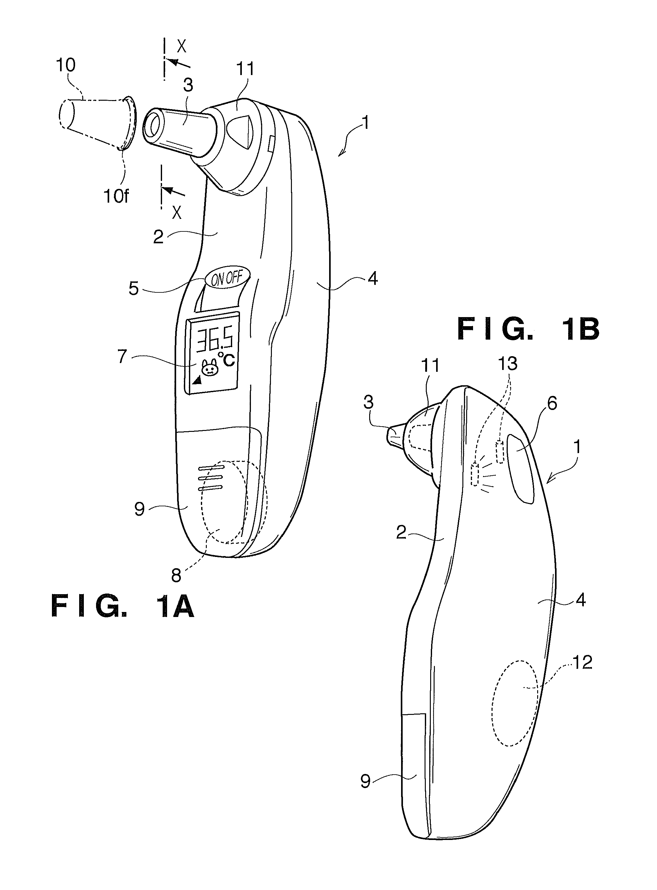
[0028]FIG. 1A is an outer perspective view of an ear thermometer 1 according to an embodiment of the present invention when viewed from the probe side and FIG. 1B is an outer perspective view of the ear thermometer 1 when viewed from the side of an operation switch 6.

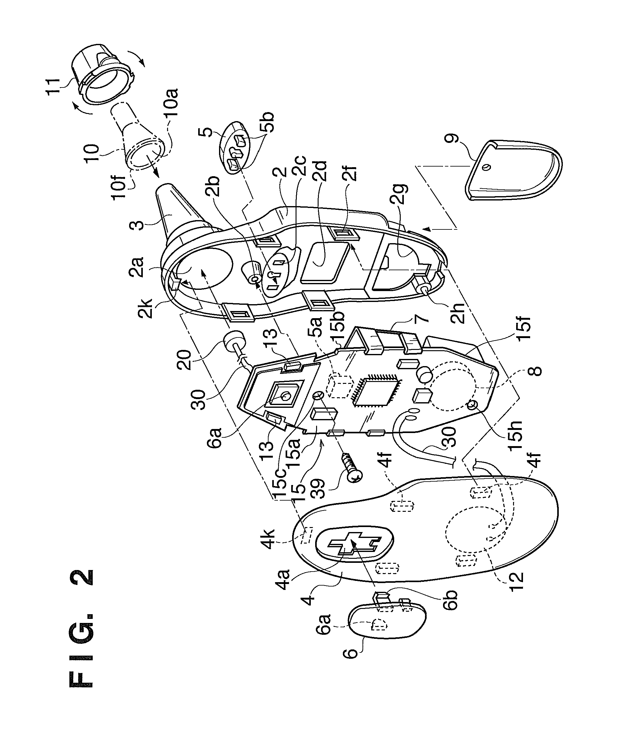
[0029]The ear thermometer 1 is configured to be separated into two components including a main body base 2 injection-molded from a predetermined resin material and a main body case 4. A mounting board (to be described later) is fixed inside the ear thermometer 1.

[0030]The main body base 2 and the main body case 4 are molded from resin materials colored in different colors. The main body case 4 is, in particular, molded from a translucent resin material. This allows a user to externally see the blinking states of two LED elements 13 provided inside through the main body case 4.

[0031]Note that resin materials which can be used for the main body case 4 are, for example, so-called enginee...

second embodiment

[0098]In the first embodiment described above, the collar portion has a disk-like shape, and at least two engaging portions 33 are formed along the inner surface. However, the present invention is not limited to this, and can use another arrangement as long as it is configured to engage the engaging portions 33 with the rear surface of the disk-like shape.

[0099]FIGS. 9A and 9B show a state in which an engaging portion 33 is annularly formed along the inner surface of a probe 3, and three projection portions 23d are formed on the edge portion of a mounting base member 23 at 120° intervals so as to radially extend.

[0100]As shown in FIG. 9B, this arrangement allows the annular engaging portion 33 formed along the inner surface of the probe 3 to support the projection portions 23d.

[0101]Note that the engaging portion 33 can be integrally formed with the probe 3 or can be formed as a separate member and fixed to the probe 3.

third embodiment

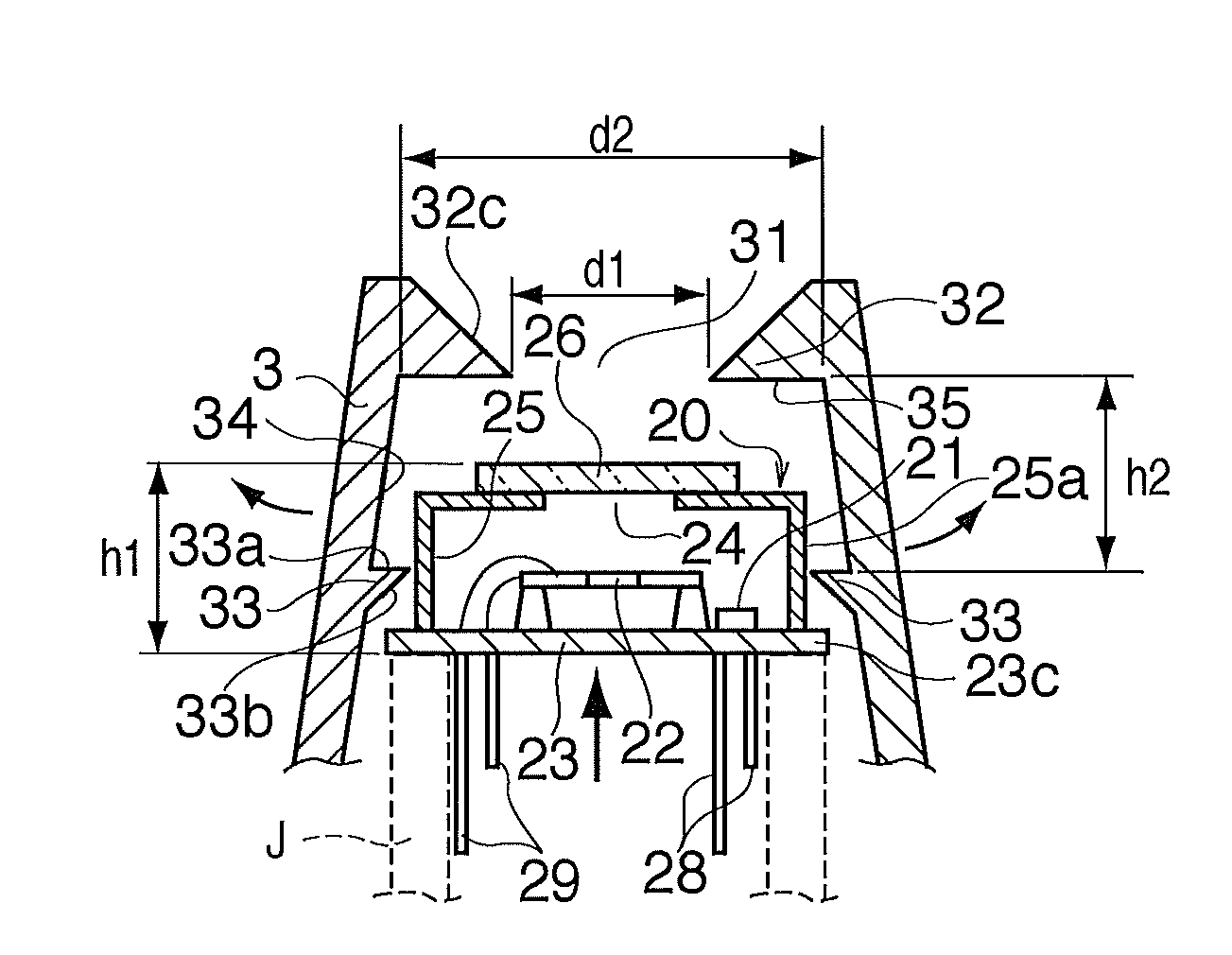
[0102]The first and second embodiments are configured such that the surface of the window member 26 of the detection element housing 20 comes into contact with the inner end face 35 so as to close the opening portion 31 of the probe 3. However, the present invention is not limited to this.

[0103]FIG. 10 shows a state in which a detection element housing 20 is fixed by bringing a container member 25 of the forcibly inserted detection element housing 20 into contact with an end face portion 32, and engaging a rear surface 23c of a mounting base member 23 with engaging portions 33.

[0104]With the arrangement shown in FIG. 10, a window member 26 is positioned in an opening portion 31 without contact with the end face portion 32.

[0105]Note that in this arrangement as well, an air layer K is formed to function as a heat insulating layer. It is therefore possible to enjoy the same advantage as that of the first embodiment, that is, being able to eliminate the influence of thermal shock due t...


PUM

PropertyMeasurementUnit
outer diameteraaaaaaaaaa
thicknessaaaaaaaaaa
outer diameteraaaaaaaaaa

Abstract

An ear thermometer which includes a temperature detection element and infrared detection element arranged near the opening portion of a probe achieves a reduction in manufacturing cost while reducing the influence of thermal shock. This invention provides an ear thermometer incorporating, in a probe, a temperature detection element to detect an environmental temperature and an infrared detection element to detect infrared radiation emitted from a temperature measurement region in an earhole. The probe includes an end face portion having an opening in its distal end, an inner surface portion of a hollow cylindrical member, and an inwardly protruding engaging portion. A detection element housing is fixed to close the opening of the probe and to form an air layer between the detection element housing and the probe.

Description

BACKGROUND OF THE INVENTION[0001]1. Field of the Invention[0002]The present invention relates to an ear thermometer and a method of manufacturing an ear thermometer.[0003]2. Description of the Related Art[0004]An ear thermometer in practical use includes a temperature detection element (e.g., a thermistor) to detect an environmental temperature and an infrared detection element (e.g., a thermopile including a cold junction and a hot junction) to detect infrared radiation emitted from a temperature measurement region in the earhole, and measures the body temperature of an object based on the detection result obtained by each detection element.[0005]For example, the present applicant has commercialized an ear thermometer which has a thermistor and a thermopile respectively arranged at positions spaced apart from the distal end of a probe (a portion to be inserted into the earhole) and measures the body temperature of an object by guiding infrared radiation incident through the opening...

Claims


Application Information

Patent Timeline
Patent Type & Authority Applications(United States)
IPC IPC(8): G01J5/10G01K1/08
CPCG01J5/04G01J5/045G01J5/049G01J2005/068G01J5/08G01J5/0893G01J5/10G01J5/06G01J5/064
Inventor YAMAGUCHI, KEIJI
Owner TERUMO KK
Why Eureka
Try Eureka