
Neuropsychological spatiotemporal pattern recognition

a spatiotemporal pattern and neuropsychological technology, applied in the field of neuropsychological spatiotemporal pattern recognition, can solve the problems of not yielding sufficiently sensitive and specific identification of flow patterns underlying specific behavioral functions, and achieve the effect of reducing the number of possible pathways

Active Publication Date: 2009-12-03
ELMINDA LTD
View PDF7 Cites 36 Cited by
  • Summary
  • Abstract
  • Description
  • Claims
  • Application Information

AI Technical Summary

Benefits of technology

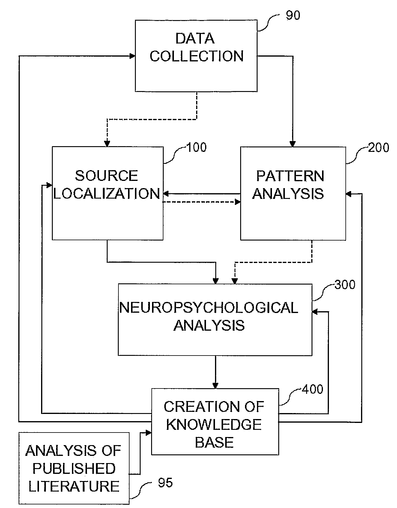
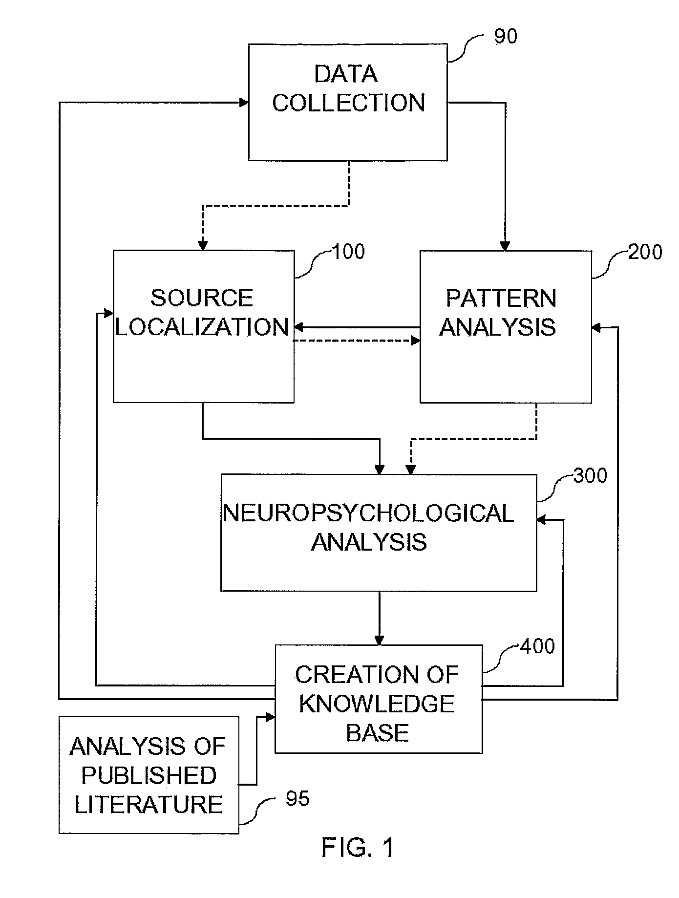
[0004]There is provided a method for establishing a knowledge base of neuropsychological flow patterns. The method includes obtaining signals from multiple research groups for a particular behavioral process, localizing sources of activity participating in the particular behavioral functions for the research groups, identifying sets of patterns of brain activity for the behavioral functions for the research groups, neuropsychologically analyzing the localized sources and the identified patterns for each of the research groups, wherein neuropsychologically analyzing includes identifying a plurality of possible pathways for the identified sets of patterns, ranking the possible pathways based on likelihood for the particular behavioral process, and reducing the number of ranked possible pathways based on additional constraints. After neuropsychologically analyzing the localized sources, the method further includes creating a set of flow patterns from the neuropsychologically analyzed sources and patterns, for each of the research groups and creating a knowledge base of the flow patterns, wherein the knowledge base is then used as a constraint for the reducing.
[0006]There is provided, in accordance with additional embodiments of the present invention, a knowledge base of flow patterns comprised of at least one set of flow patterns corresponding to a neuropsychological behavior. The set of flow patterns is established based on identification and neuropsychological analysis of patterns of brain activity from multiple subjects during performance of the neuropsychological behavior, and the set may be compared to a flow pattern obtained from an individual subject. Moreover, the knowledge base may be used to further enhance the identification and neuropsychological analysis.

Problems solved by technology

The flow of activity among those regions is often synchronization-based, even at the millisecond level and sometimes with specific time delays.
Although it is known that multiple regions play a role and that the flow from one region to another is important, there are currently very few methods for patterning this flow and relating the patterns to particular tasks, and those methods which do attempt to pattern the flow do not seem to yield sufficiently sensitive and specific identification of the flow patterns underlying specific behavioral functions and pathologies.

Method used


Image

  • Neuropsychological spatiotemporal pattern recognition
  • Neuropsychological spatiotemporal pattern recognition
  • Neuropsychological spatiotemporal pattern recognition

Examples


first embodiment

[0048]Reference is now made to FIGS. 9 and 10, taken together, where FIG. 9 is a flow chart diagram illustration of a method of pattern analysis 200, in accordance with the present invention wherein source localization is performed prior to pattern analysis, and FIG. 10 is a graphical illustration of a step of pattern analysis 200, as will be described hereinbelow. First, locations found by source localizer 20 are mapped (step 202) onto 3-D grids over time. As shown in FIG. 10, at each time period, a different three-dimensional map of the various locations is generated, showing (step 204) signal strengths at locations for a primary time period A and a secondary time period B. Additional time periods may be included as well. Generally, the signal strengths and their spatial distributions change after a period of time (usually in the milliseconds—up to tens of milliseconds range). Thus, for example, at one time, particular localizations may demonstrate particular signal strengths (sho...

second embodiment

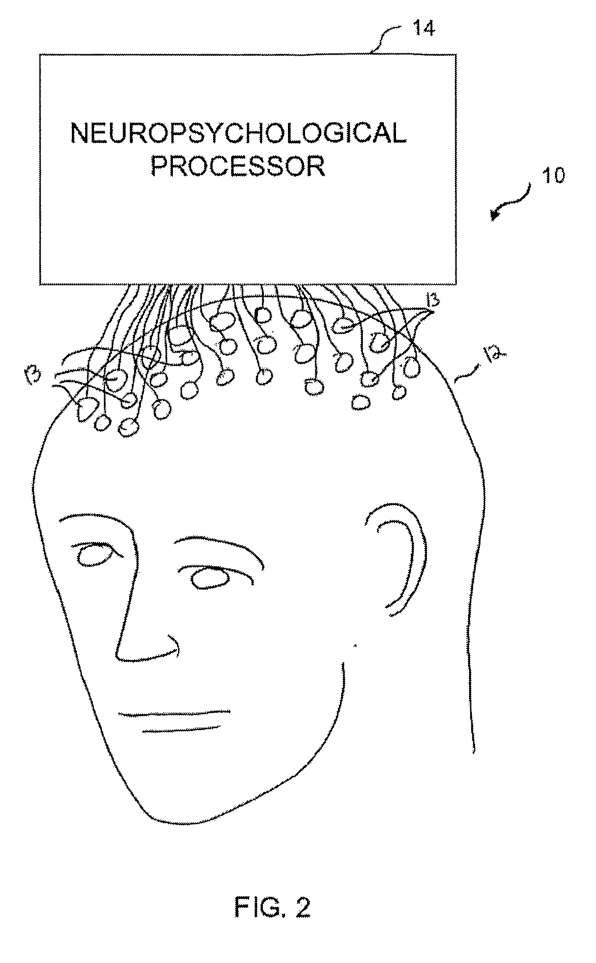
[0076]Reference is now made to FIG. 23, which is a block diagram illustration of processor 604, showing the components in greater detail. Processor 604 includes an input adjustor 610, a pattern comparator 612 and a copy of knowledge base 16 created from experimental and published information, as described above. Input adjustor 610 is configured to adjust input from signal collector 602 so that it conforms to the flow pattern information found in knowledge base 16. Thus, in one embodiment, input adjustor 610 includes a source localizer 20 and is configured to perform source localization so as to identify regions of the brain being activated by the activity or task performed by testing subject 603. In another embodiment, input adjustor 610 is configured to identify peaks, wavelets, or other discrete identifiable elements over time for electrodes 13. In this second embodiment, the knowledge base patterns are also described at this electrode level. Pattern comparator 612 then takes the ...


PUM


Abstract

Systems and methods for identifying and analyzing neuropsychological flow patterns, include creating a knowledge base of neuropsychological flow patterns. The knowledge base is formed by obtaining signals from multiple research groups for particular behavioral processes, localizing sources of activity participating in the particular behavioral processes, identifying sets of patterns of brain activity for the behavioral processes and neuropsychologically analyzing the localized sources and the identified patterns for each of the research groups. The neuropsychological analysis includes identifying all possible pathways for the identified sets of patterns, ranking the possible pathways based on likelihood for the particular behavioral process and reducing the number of ranked possible pathways based on additional constraints. A system for comparison of obtained signals from an individual to the created knowledge base is provided. These obtained signals are then used to further update the existing knowledge base.

Description

FIELD OF THE INVENTION[0001]The present invention relates to methods of functional brain imaging and, more particularly, to methods for modeling and / or diagnosing particular neuropsychological functions via spatiotemporal flow patterns among functional brain regions.BACKGROUND OF THE INVENTION[0002]It is known in the field of neuropsychology that behavioral functions are based upon flow among various functional regions in the brain, involving specific spatiotemporal flow patterns. Likewise, behavioral pathologies are often indicated by a change in the patterns of flow. The specific spatiotemporal pattern underlying a certain behavioral function or pathology is composed of functional brain regions, which are often active for many tens of milliseconds and more. The flow of activity among those regions is often synchronization-based, even at the millisecond level and sometimes with specific time delays.[0003]Currently, methods for relating behavioral functions to their underlying local...

Claims


Application Information

Patent Timeline
IPC IPC(8): G06K9/00G16Z99/00
CPCG06K9/00543G06K9/6224G06F19/3437G06F17/18G16H50/50G16Z99/00G06F2218/14G06F18/2323A61B5/245A61B5/374A61B5/7246A61B5/7275
Inventor SHAHAF, GODEDGEVA, AMIR B.
Owner ELMINDA LTD
Learn More