Illuminative light communication system, lighting device and illuminative light source

a technology of light communication system and lighting device, which is applied in the direction of powerline communication application, identification means, instruments, etc., can solve the problems of radio wave radiation not developing and bandwidth restriction

Inactive Publication Date: 2009-12-03
NAKAGAWA LAB INC
View PDF11 Cites 73 Cited by
  • Summary
  • Abstract
  • Description
  • Claims
  • Application Information

AI Technical Summary

Benefits of technology

[0008]Note that the optical transmitting / receiving unit is deployed in multiple positions in different communication directions, and data received by a certain light transmitting / receiving unit can be optically transmitted through the air from another light transmitting / receiving unit to the device. As a result, the lighting devices can be deployed freely, and data transmission is possible regardless of the positions of the lighting devices. In addition, the light transmitting / receiving unit allows bi-directional optical communication through the air with another device. Furthermore, since the plurality of lighting units includes a light receiving unit that receives light modulated in accordance with data emitted from a terminal device, which receives emitted light and thereby receives data, optical bidirectional communication among the terminal device and the plurality of lighting units is possible. The plurality of illuminative light emitting units uses a semiconductor light emitting device such as an LED as an illuminative light source. The plurality of lighting units can be an indoor illumination lamp or a street lamp.
[0010]In this manner, by providing the optical transmitting / receiving unit and the control unit in the illuminative light source, construction of an illuminative light communication system using the existing lighting device, merely with simple electrical work such as replacement of a fluorescent lamp or an electric bulb with an illuminative light source according to the present invention becomes possible.

Problems solved by technology

On the other hand, it is unnecessary when carrying out optical communication via the air.
In addition, different than power line communication, problems such as restriction on bandwidths and radio wave radiation do not develop.

Method used


Image

  • Illuminative light communication system, lighting device and illuminative light source
  • Illuminative light communication system, lighting device and illuminative light source
  • Illuminative light communication system, lighting device and illuminative light source

Examples


first embodiment

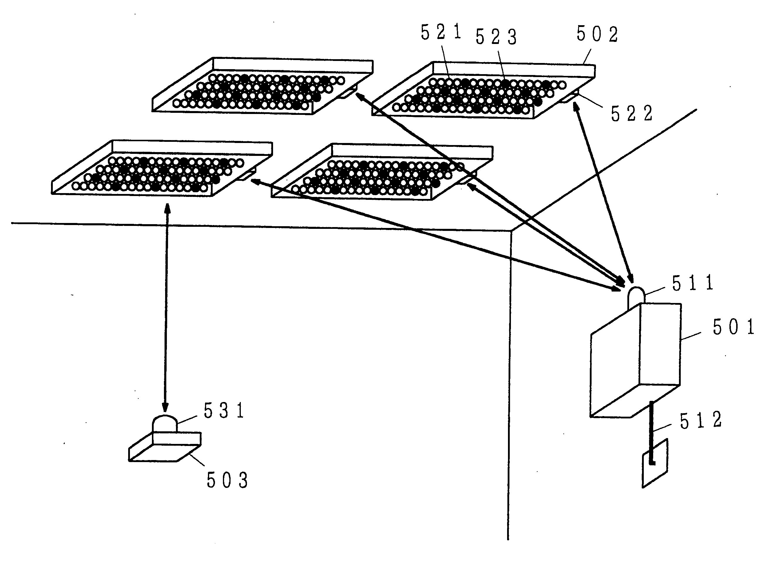
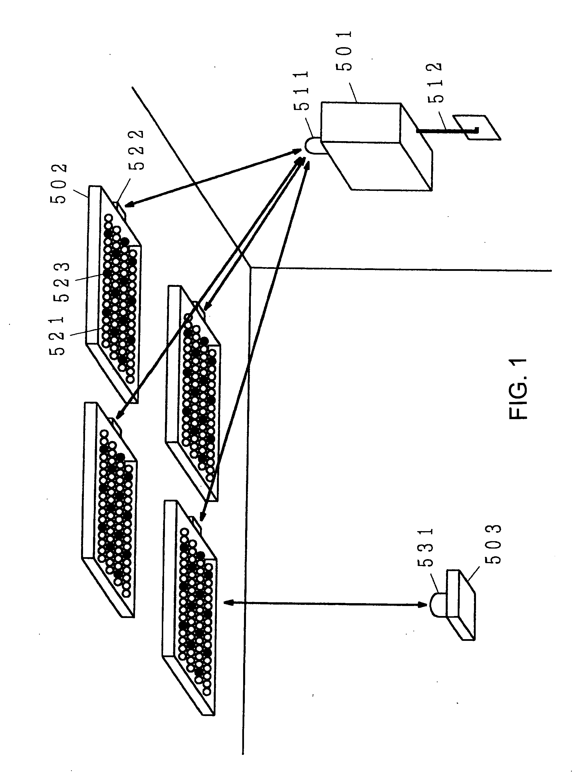
[0029]FIG. 1 is an explanatory diagram of an illuminative light communication system, according to the present invention. In the drawing, 501 denotes an optical communication device, 502 denotes lighting elements, 503 denotes a terminal device, 511, 522, and 531 denote light transmitting / receiving units, 512 denotes a communication cable, 521 denotes light emitting devices, and 523 denotes light reception devices. In the example shown in FIG. 1, an illuminative light communication system is structured using lighting elements provided for indoor lighting.

[0030]The optical communication device 501, which transmits to the lighting elements 502 data that is to be sent by them through illuminative light communication, is provided indoors. The optical communication device 501 is connected to the network, and transmits / receives data via the network. The network is a wired network, which is provided in offices, schools, plants, and homes, and is configured from an optical fiber, a coaxial c...

second embodiment

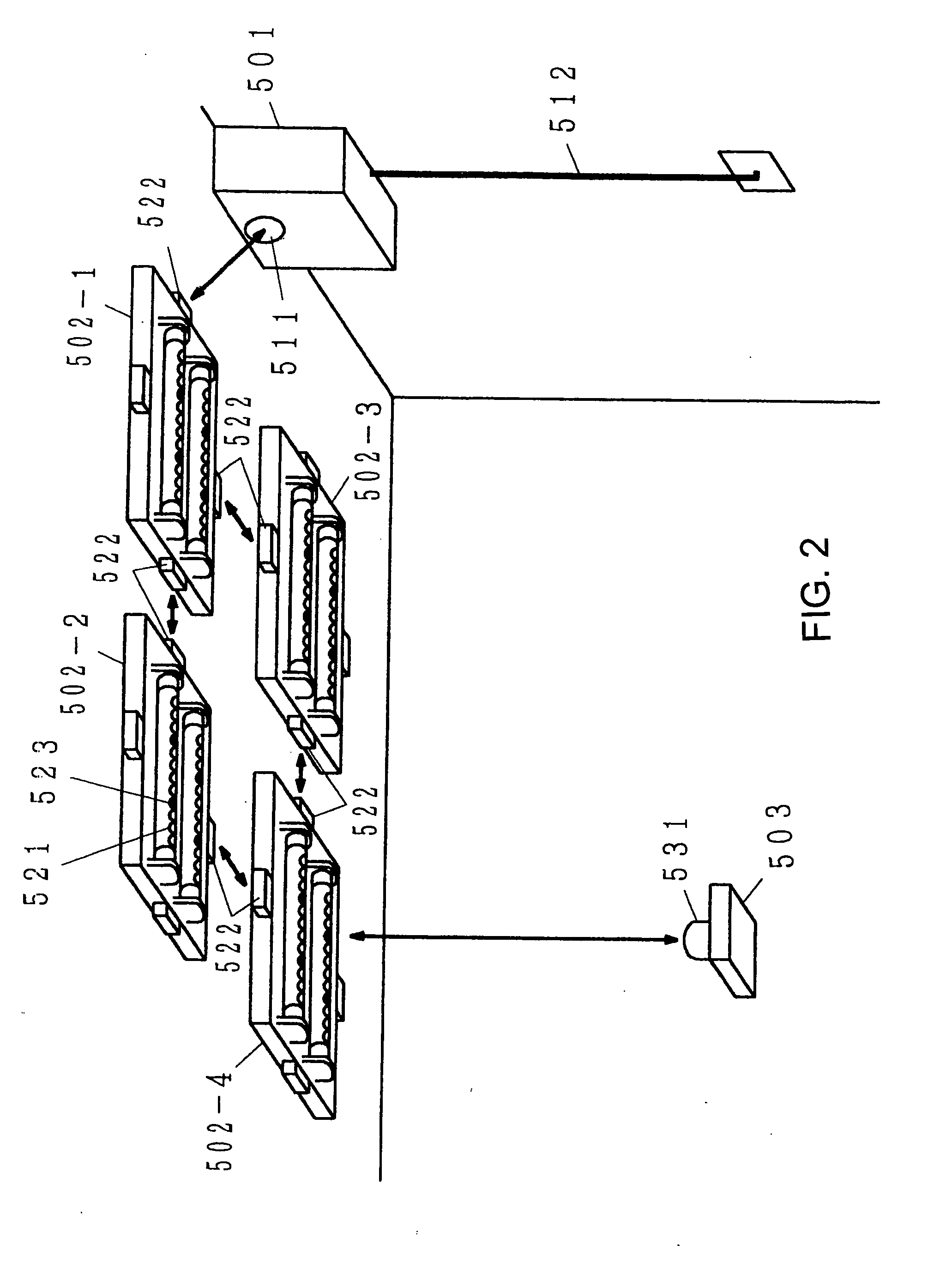
[0043]In the second embodiment, as shown in FIG. 3, light transmitting / receiving units 522 are provided on all four sides of the lighting elements 502, and allow communication among the lighting elements 502. In addition, only the light transmitting / receiving units 522 of any one or multiple lighting elements 502 communicate with the optical communication device 501. Other lighting elements 502, which do not communicate directly with the optical communication device 501, transmit / receive data by communicating with another lighting element 502.

[0044]In the example shown in FIG. 2, the lighting element 502-1 communicates directly with the optical communication device 501. The lighting elements 502-2 and 502-3 communicate with the lighting element 502-1 to receive / transmit data from / to the optical communication device 501. The lighting element 502-4 communicates with the lighting element 502-2 or 502-3 to receive / transmit data from / to the optical communication device 501. For example, ...

fifth embodiment

[0054]In the example shown in FIG. 9, for example, the shape of the illuminative light sources 551, according to the present invention, is the same rod shape as strip lights as with the example shown in FIG. 3. The illuminative light sources 551 each comprises light emitting devices 521, light reception devices 523, and a controller not shown in the drawing. In addition, the inter-adjacent light source light transmitting / receiving units 552 are provided on the tube and are used for communication between adjacent illuminative light sources 551 when the illuminative light sources 551 are positioned so as to provide multiple fluorescent lamps in parallel. Note that assuming the case of providing three or more of illuminative light sources 551, the inter-adjacent light source light transmitting / receiving units 552 should be provided on both sides of the tube.

[0055]In addition, the inter-lighting element light transmitting / receiving units 553 are provided for communicating with illuminat...


PUM


Abstract

Information received from a wired network terminal on the wall face, or the like, is delivered as a light signal from a light transmitting / receiving section of a light communication unit. A lighting fixture is provided with a light transmitting / receiving section where light is received from the light communication unit in order to acquire information, and a light emitting element emits illumination light modulated according to that information. A terminal can acquire the information by receiving the illumination light at a light transmitting / receiving section. Since communication is performed from the light communication unit to the terminal by irradiating light into the space, a convenient illumination light communication system requiring no communication cable or laying work of optical fibers can be constructed.

Description

CROSS-REFERENCES TO RELATED APPLICATIONS[0001]This application is a continuation of U.S patent application Ser. No. 10 / 532,250 filed Oct. 23, 2003, as International Application No. PCT / JP03 / 013539, now pending, the contents of which, including specification, claims and drawings, are incorporated herein by reference in their entirety. This application claims priority from Japanese Patent Application Ser. No. 2003-084819 filed Mar. 26, 2003, the contents of which are incorporated herein by reference in their entireties.BACKGROUND OF THE INVENTION[0002]The present invention aims to provide an illuminative light communication system that does not require electrical work for providing a cable or an optical fiber, and prevents problems such as restriction on bandwidths, radio wave radiation, and superimposition of noise from developing, which is different than power line communication, and a lighting device and an illuminative light source used for such illuminative light communication sy...

Claims


Application Information

Patent Timeline
Patent Type & Authority Applications(United States)
IPC IPC(8): H04B10/10G09F9/33H04B3/54H04B10/114H04B10/116
CPCF21Y2101/02G09F9/33H01L2924/3025F21K9/10F21V33/0052H01L2224/48247H01L2224/48091H01L25/0753H04B3/54H04B10/1141H04B10/1149H04B10/116H04B2203/5412H04B2203/5458H05B37/0263H05B37/0272Y02B20/72H01L2924/00014H01L2924/00F21K9/20F21Y2115/10F21K9/65H05B47/185H05B47/195H05B47/1965F21S8/08G08B27/00
Inventor NAKAGAWA, MASAOKOMINE, TOSHIHIKOHARUYAMA, SHINICHIRO
Owner NAKAGAWA LAB INC
Why Eureka
Try Eureka