
Fixing apparatus

Active Publication Date: 2009-12-03
SHARP KK
View PDF7 Cites 8 Cited by
  • Summary
  • Abstract
  • Description
  • Claims
  • Application Information

AI Technical Summary

Benefits of technology

[0016]The present invention intends to provide a fixing apparatus that has a mechanism including a turnable cam as described above and is capable of recovering the operations of a mechanism with ease even if the mechanism enters a locked state due to some problem or the like having occurred to the mechanism.
[0018]With such a configuration, the fixing apparatus including the switching portion having the mechanism using the turnable cam as described above can recover the operations of the switching portion with ease by performing the aforementioned forward rotational direction retry control even if some problem or the like occurred to the switching portion so that the switching portion enters a locked state. Thus, the stoppage of operations in the fixing apparatus can be easily suppressed. Furthermore, it is not necessary to use a larger scaled motor or the like to turn the aforementioned cam than necessary, thus enabling the suppression of increases in the cost of the fixing apparatus.
[0021]By doing this, excessive force can be suppressed from being exerted onto the switching portion for the fixing apparatus for a long time.
[0024]By doing this, in the fixing apparatus including the switching portion having a mechanism using the turnable cam as described above, similarly to the aforementioned case of shifting from the pressure applied state to the pressure released state, also in the case of shifting from the pressure released state to the pressure applied state, even if some problem or the like occurs to the switching portion so that the switching portion enters a locked state, the operations of the switching portion can be recovered with ease by performing the aforementioned backward rotational direction retry control. Thus, the stoppage of operations in the fixing apparatus can be easily suppressed. Furthermore, it is not necessary to use a larger scaled motor or the like to turn the aforementioned cam than necessary, thus enabling the suppression of increases in the cost of the fixing apparatus.
[0027]By doing this, the exertion of excessive force onto the switching portion for the fixing apparatus for a long time can be suppressed.
[0030]Therefore, in the fixing apparatus including the switching portion having the mechanism using the aforementioned turnable cam, even if some problem or the like occurs to the switching portion so that the switching portion enters a locked state, the operations of the switching portion can be recovered with ease by performing the aforementioned forward rotational direction retry control or backward rotational direction retry control. Thus, the stoppage of operations in the fixing apparatus can be easily suppressed. Furthermore, it is not necessary to use a larger scaled motor or the like to turn the aforementioned cam than necessary, thus enabling the suppression of increases in the cost of the fixing apparatus.

Problems solved by technology

When the cam is turned, some problem or the like may occur to the mechanism of the cam so that the mechanism enters a locked state.
In order to forcibly turn the cam when such a state occurs, it is necessary to use a larger scaled motor or the like to turn the cam than necessary; thus, the cost of the fixing apparatus may possibly increase.

Method used


Image

  • Fixing apparatus
  • Fixing apparatus
  • Fixing apparatus

Examples


Embodiment Construction

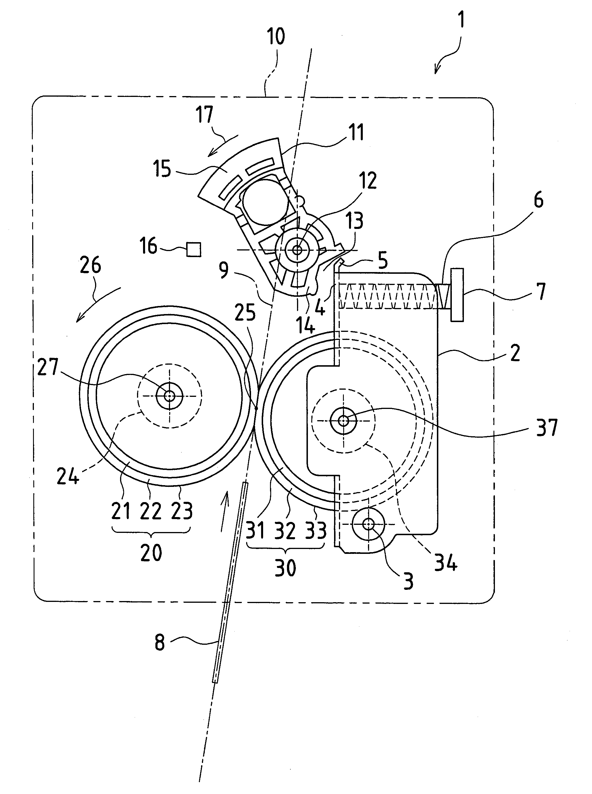
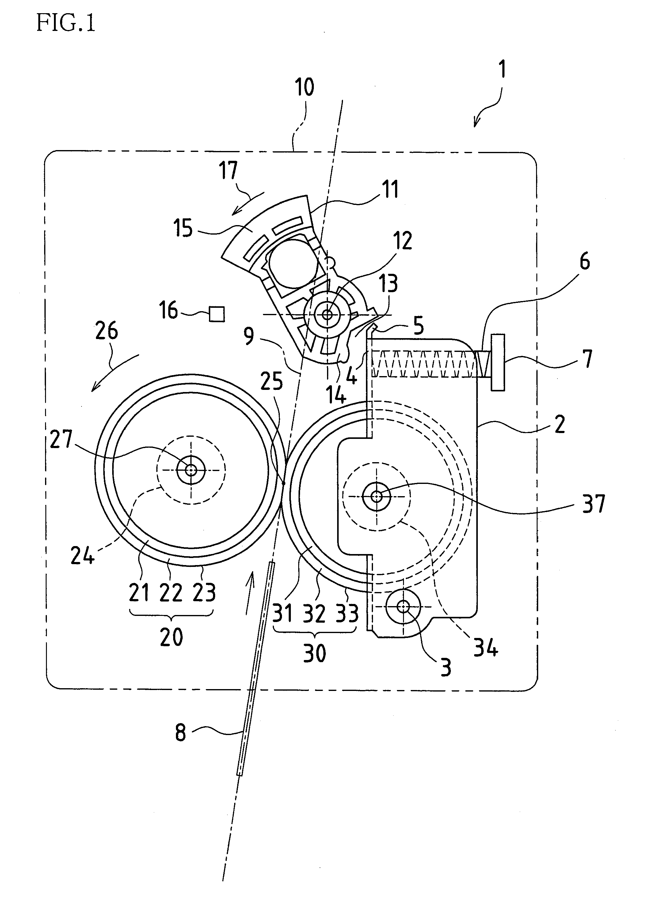
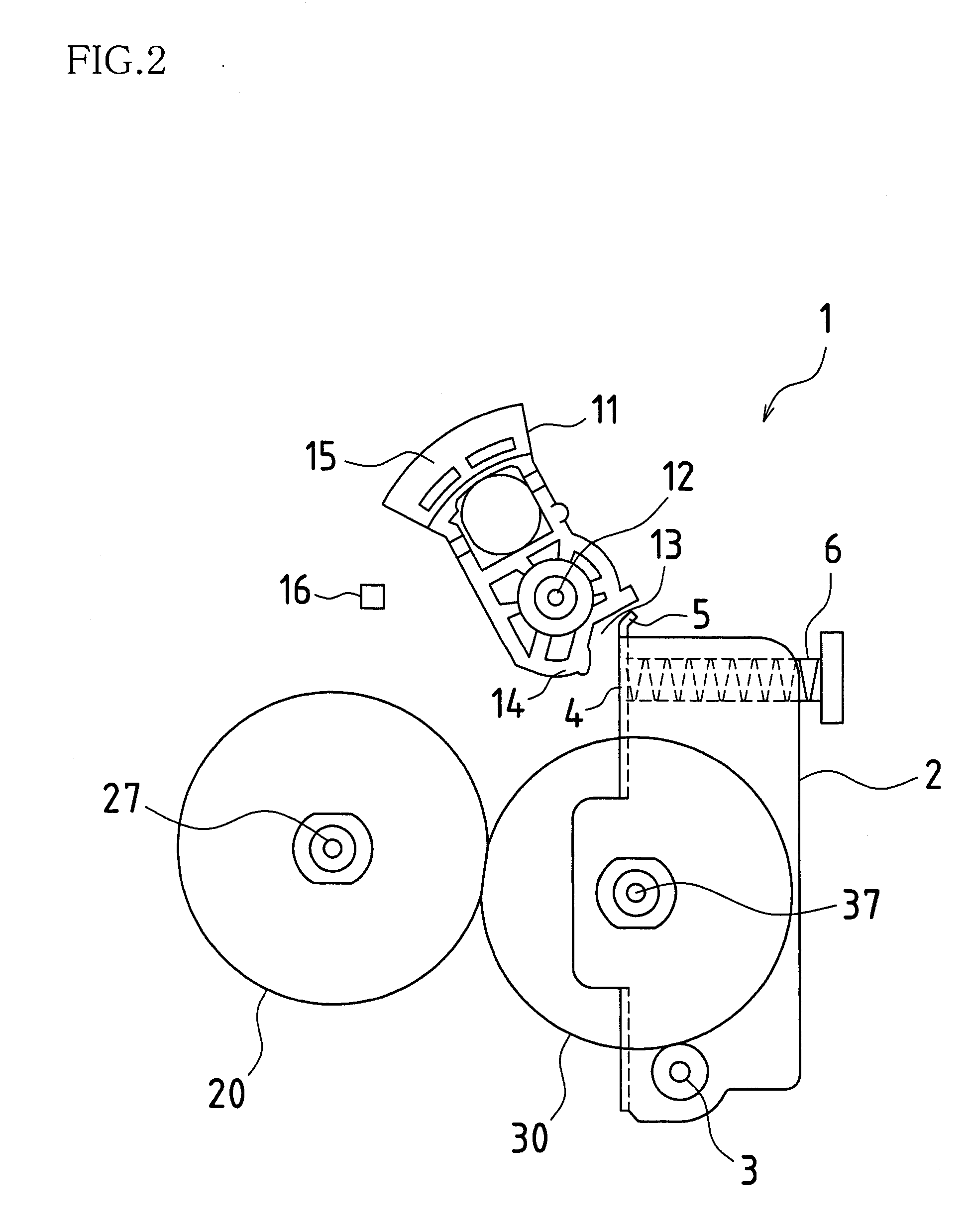
[0042]A fixing apparatus in an embodiment of the present invention will be described with reference to the drawings. FIG. 1 is a configuration diagram showing the configuration of a fixing apparatus 1 in the present embodiment. In FIG. 1, the fixing apparatus 1 in the present embodiment is mainly configured of a hot roller 20 and a pressure roller 30, which form a pair of rotary bodies, a pressure roller holder 2, a spring 6, a pressure control lever (cam) 11, a sensor 16, and a fixing apparatus chassis 10. The aforementioned pressing portion is mainly configured of a combination of the pressure roller holder 2 and the spring 6 among the above components. Also, the aforementioned switching portion is configured of the pressure control lever 11.

[0043]Note that, in FIG. 1, the fixing apparatus chassis 10 is formed in front of the hot roller 20, the pressure roller 30, the pressure roller holder 2, the spring 6, the pressure control lever 11, the sensor 16, and the like, and the fixing...


PUM


Abstract

In one embodiment, a fixing apparatus is configured of a pressing portion for causing the pressure roller to enter a pressure applied state by applying bias, a switching portion for causing the pressing portion in the pressure applied state to enter a pressure released state by causing a cam to rotate forward, a pressure state detection portion for detecting the pressure released state, and a control portion for, when shifting from the pressure applied state to the pressure released state, turning forward the cam of the switching portion in the pressure applied state and stopping the cam after the pressure state detection portion detects the pressure released state. If the cam is turned forward with respect to the switching portion for a certain time period, but the pressure state detection portion does not detect the pressure released state, the control portion performs forward rotational direction retry control.

Description

CROSS-REFERENCE TO RELATED APPLICATIONS[0001]This application claims priority under 35 U.S.C. §119(a) on Patent Application No. 2008-138183 filed in Japan on May 27, 2008, the entire contents of which are herein incorporated by reference.BACKGROUND OF THE INVENTION[0002]1. Field of the Invention[0003]The present invention relates to a fixing apparatus used in an image forming apparatus and the like.[0004]2. Related Art[0005]In an image forming apparatus and the like using an electrophotographic method that is widely applied in copying machines, laser printers, facsimiles, and the like, conventionally, a fixing method used in a fixing apparatus is generally a heat fixing method. For such a heat fixing method, a hot roller fixing method using a hot roller is generally applied.[0006]With the hot roller fixing method, a hot roller, that includes an internal heater as a heat source and an external surface covered with rubber or resin having good releasability, and a pressure roller are p...

Claims


Application Information

Patent Timeline
IPC IPC(8): G03G15/20
CPCG03G15/2032
Inventor YAMANAKA, TAKASHIIDE, ATSUSHITSUKAMOTO, KIMIHIDENAKATANI, HIROSHI
Owner SHARP KK
Learn More