Fuel pump and method of manufacturing the same

a technology of fuel pump and fuel pump body, which is applied in the direction of pump, positive displacement liquid engine, machine/engine, etc., to achieve the effect of reducing electrochemical corrosion of terminals and high electric conductivity

Active Publication Date: 2009-12-03
AISAN IND CO LTD
View PDF2 Cites 10 Cited by
  • Summary
  • Abstract
  • Description
  • Claims
  • Application Information

AI Technical Summary

Benefits of technology

[0006]The present invention is made in view of the foregoing matter, and it is an object of the present invention to provide a fuel pump capable of reducing electrochemical corrosio...

Problems solved by technology

In the fuel pump for the alcohol mixture fuel, therefore, it is required to restrict an electrical short circuit between a positive electrode terminal and a negative ele...

Method used


Image

  • Fuel pump and method of manufacturing the same
  • Fuel pump and method of manufacturing the same
  • Fuel pump and method of manufacturing the same

Examples


Embodiment Construction

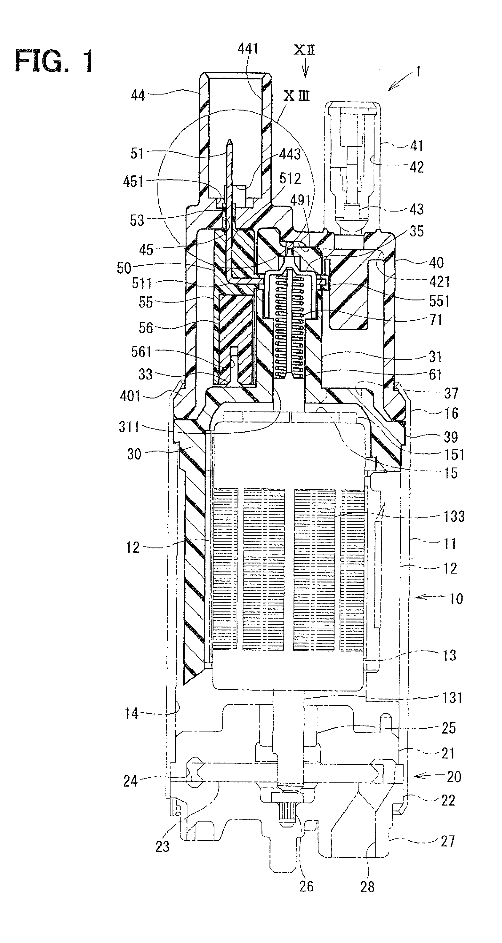
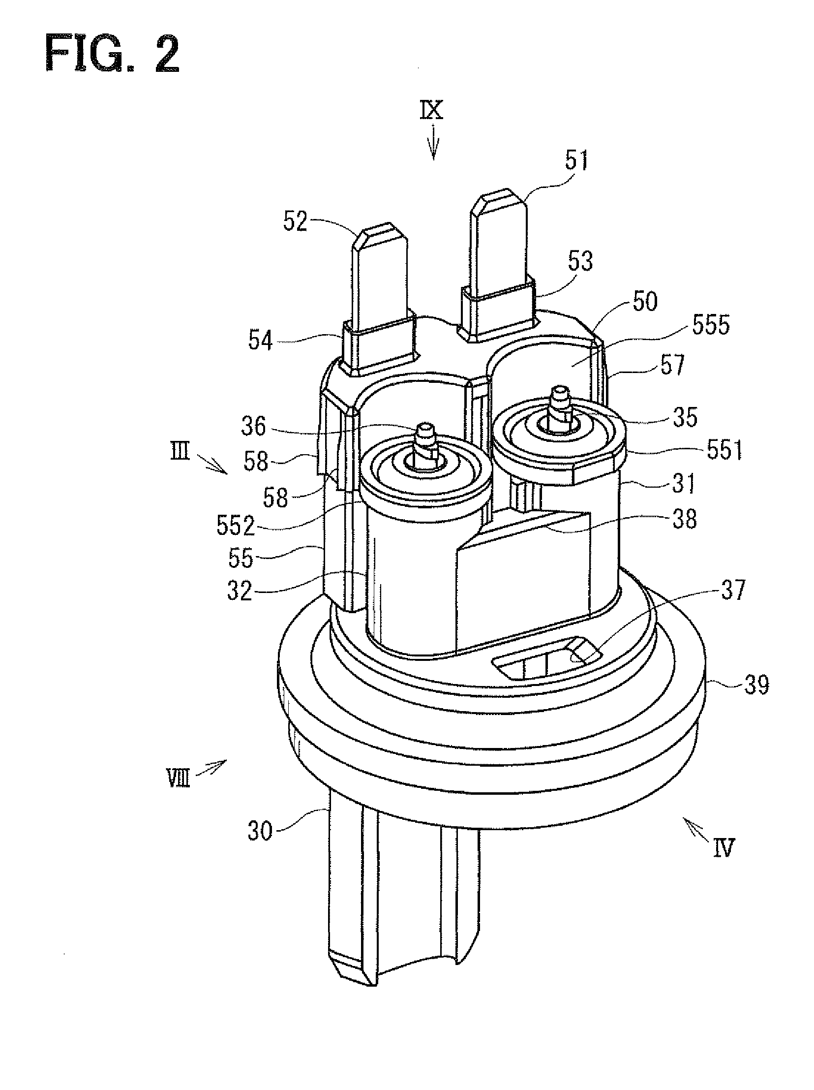
[0032]An exemplary embodiment of the present invention will now be described with reference to FIGS. 1 to 21.

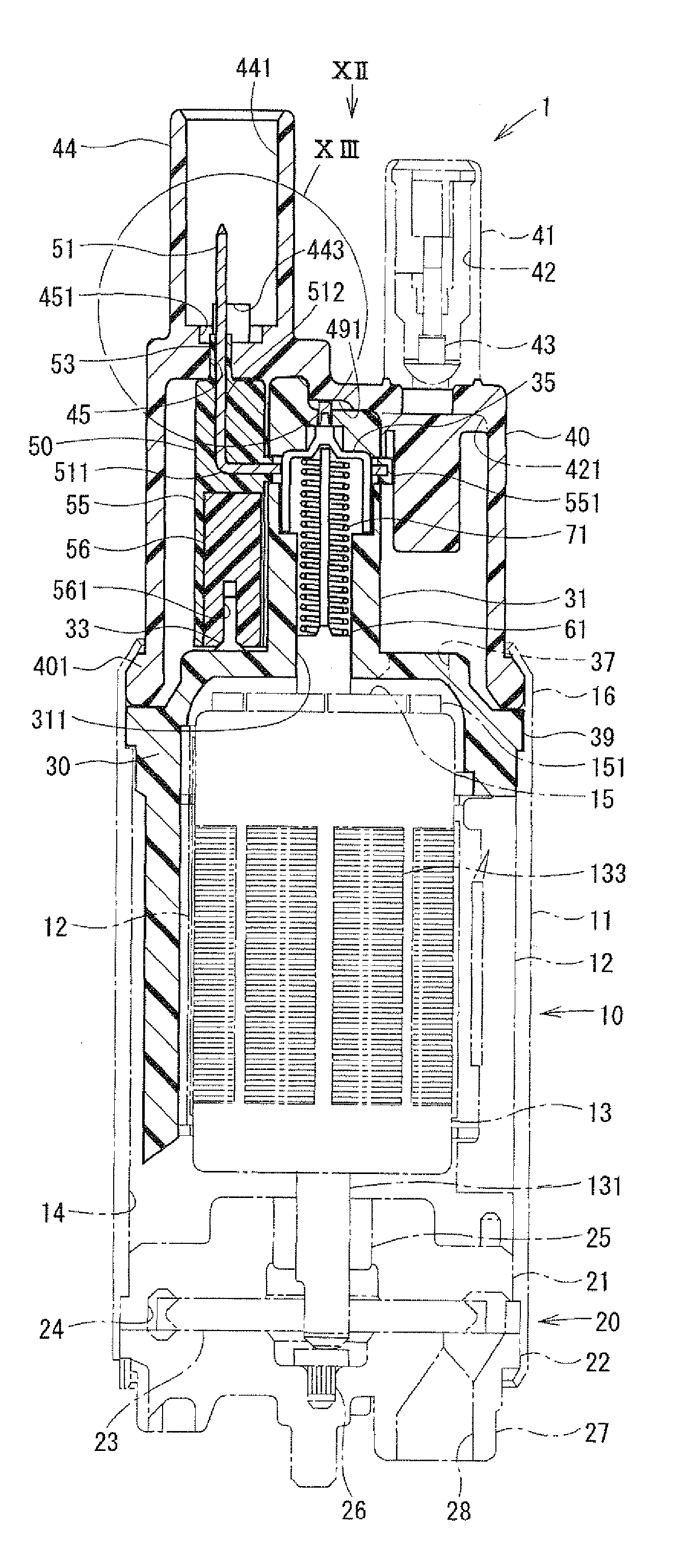
[0033]Referring to FIGS. 1 to 14, a fuel pump 1 of the present embodiment is an in-tank fuel pump mounted inside of a fuel tank of a vehicle and the like, for example. Thus, the fuel pump 1 is used in a condition where an entirety thereof is submerged in fuel. The fuel pump 1 serves to feed the fuel inside of the fuel tank to an engine of the vehicle. Here, the fuel is the alcohol mixture fuel containing a component having high electric conductivity, such as the high density alcohol fuel, bio-ethanol, ethanol 100% fuel and the like.

[0034]A schematic structure of the fuel pump 1 will be described first with reference to FIG. 1. In FIG. 1, components existing on a front side (near side) with respect to components shown in solid cross-section are shown by chain line for convenience of illustration.

[0035]The fuel pump 1 generally includes a motor section 10 and a pump section 20 ...


PUM

PropertyMeasurementUnit
Lengthaaaaaaaaaa
Widthaaaaaaaaaa
Distanceaaaaaaaaaa

Abstract

A fuel pump includes a case member defining a fuel passage and a discharge-side cover connected to the case member and defining an outlet port. A pump section has an inlet port and is connected to the case member. A motor section is housed in the case member for driving the pump section. A positive electrode terminal and a negative electrode terminal are supported by an insulative terminal support member fixed to the discharge-side cover. Base portions of the positive and negative electrode terminals are covered by insulative portions. The insulative portions are fitted in fitting holes of the discharge-side cover. The discharge-side cover has guide portions on its inner surface. The terminal support member has engagement projections on opposite side walls thereof. The engagement projections are guided by the guide portions to restrict the discharge-side cover from rotating with respect to the terminal support member.

Description

CROSS REFERENCE TO RELATED APPLICATION[0001]This application is based on Japanese Patent Application No. 2008-140165 filed on May 28, 2008, the disclosure of which is incorporated herein by reference.FIELD OF THE INVENTION[0002]The present invention relates to a fuel pump and a method of manufacturing the same.BACKGROUND OF THE INVENTION[0003]An electric fuel pump having a pump section and a motor section within a case member is, for example, described in US Patent Application Publication No. 2008 / 0063545 (JP-A-2008-64027, JP-A-2008-64029). In such a fuel pump, fuel is suctioned from a fuel suction portion of the pump section. The fuel is increased in pressure through the pump section, and then flows through a peripheral area of the motor section. Then, the fuel is discharged to the outside of the fuel pump from a discharge port of a discharge-side cover disposed on an end of the motor section opposite to the pump section.[0004]The pump section is supplied with electric power from a...

Claims


Application Information

Patent Timeline
IPC IPC(8): F04B37/02B23P15/00
CPCF02M37/08Y10T29/49236F04D5/002F02M2037/082
Inventor TAKAGI, MASATOSHIITO, MOTOYA
Owner AISAN IND CO LTD
Why Eureka
Try Eureka