Check patentability & draft patents in minutes with Patsnap Eureka AI!

Self-Ligating Orthodontic Bracket

Inactive Publication Date: 2009-12-03
WEI YU CHEN +1
View PDF2 Cites 32 Cited by
  • Summary
  • Abstract
  • Description
  • Claims
  • Application Information

AI Technical Summary

Benefits of technology

[0010]An object of the present invention is to provide a self-ligating orthodontic bracket with an internalized structure for engaging a main body with a cover to prevent food debris from being accumulated on the surface of the self-ligating orthodontic bracket.
[0011]Another object of the present invention is to provide a self-ligating orthodontic bracket having an engagement structure for connecting the main body with the cover, where the cover has better structural strength by the design of the engagement structure, so that the cover will not be deformed easily after a period of using.
[0012]Another object of the present invention is to provide a self-ligating orthodontic bracket, wherein the main body and the base are assembled after manufactured, so that the surface of the base attaching to the outer surface of a tooth can be optimized to strengthen the adhering ability thereof.

Problems solved by technology

However, during orthodontic process, there are still some crevices between the digital protrusion and the combed recess and food debris are easily accumulated within these crevices.
With the accumulation of food debris in the crevices, bacteria will grow easily and rapidly and teeth will be affected consequently.
Moreover, the accumulation of food debris will also affect the cover's normal opening and closing and thus results in abnormal performance of the orthodontic bracket.
Furthermore, when dovetail structure is used as the means for the engagement of the cover and the body, parts of the cover and the body involved in the engagement are usually structurally weakest.
Owing to this design limitation, it is difficult to optimize the surface of the pad attaching to the outer surface of a tooth and the adhering ability of the conventional self-ligating orthodontic bracket is weakened.

Method used


Image

  • Self-Ligating Orthodontic Bracket
  • Self-Ligating Orthodontic Bracket
  • Self-Ligating Orthodontic Bracket

Examples


Embodiment Construction

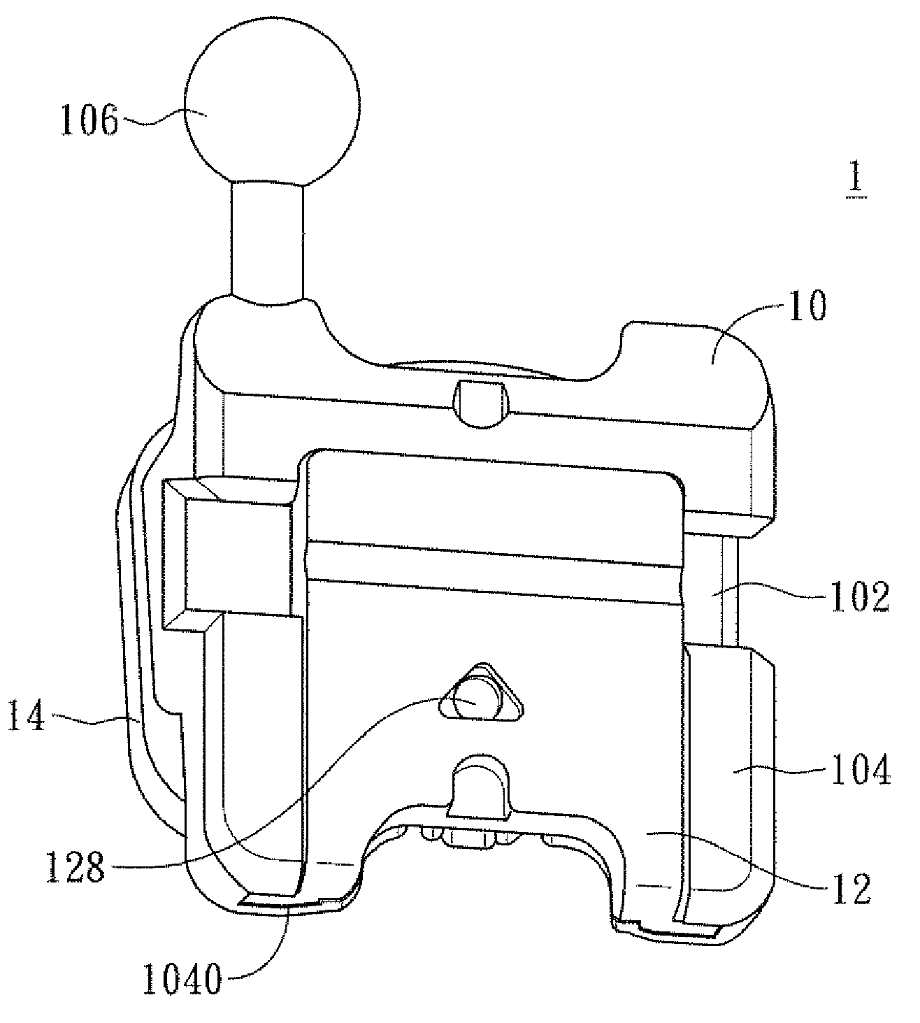
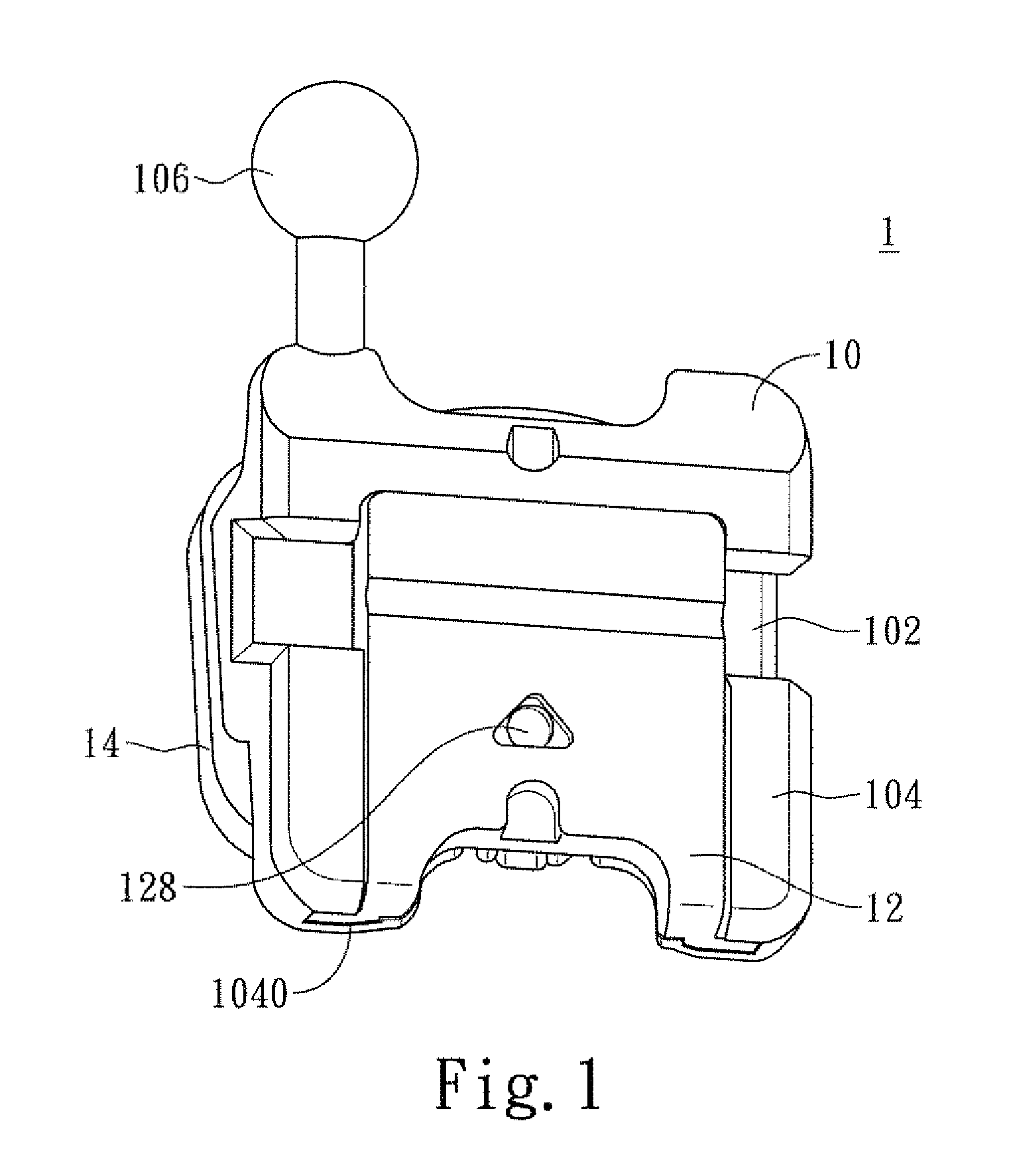
[0026]The present invention relates to a self-ligating orthodontic bracket 1 comprising a main body 10, a cover 12, and a base 14 connected to the bottom of the main body 10.

[0027]Please refer to FIGS. 1, 4, 5 and 6 of the present invention. As shown in above figures, the main body 10 is provided with a slot 102 at one end on the top thereof for receiving an arch wire in orthodontic purpose. Besides, the main body 10 has a connecting part 104 near the slot 102 and a hook 106 at the front end thereof. The connecting part 104 is provided respectively with a track 1040 at two lateral sides thereof and has an engaging part 1042 at one end on the top thereof Besides, a stop track 1044 is provided at each of the two locations adjacent to two lateral sides of the engaging part 1042.

[0028]The cover 12 includes two connections 122, two stop parts 124, a protrusion 126, and a recess 128 located on the top of the cover 12 The connections 122 are disposed at two lateral sides of the cover 12 re...


PUM


Abstract

A self-ligating orthodontic bracket, comprising a main body provided with a slot at one end of the top thereof for placing an arch wire therein and a base fixed to the bottom of the main body, is adhered to the outer surface of a tooth via the bottom of the base and is characterized in that: the main body is detachably connected with a cover, where the main body comprises a connecting part and at least an engaging part. The connecting part is located at one end near the slot and is provided with at least a track at two lateral sides respectively. The engaging part is provided at one end of the connecting part. The cover has two lateral sides that are in sliding connection with the tracks and is provided with at least a protrusion on its bottom for engagement with the engaging part. Thereby, the cover can be open or closed conveniently for users to place an arch wire into the slot or remove the arch wire out of the slot.

Description

BACKGROUND OF THE INVENTION[0001]1. Field of the Invention[0002]The present invention relates to an orthodontic bracket and, more particularly, to a self-ligating orthodontic bracket, which is pleasing in appearance and easy to operate, has better structural strength and better adhering ability toward the surface of a tooth, and is designed to avoid the accumulation of food debris thereon.[0003]2. Description of the Prior Art[0004]Conventionally, various orthodontic braces (or brackets) are used for orthodontic purpose. The principle of orthodontics is to apply force produced from an arch wire to teeth for correcting alignment of teeth and their positions with regard to occlusion. Thereby, various flaws of teeth and jaws can be corrected.[0005]With the popularization of orthodontics, various orthodontic braces emerge in the market correspondingly. Self-ligating orthodontic brackets are newer products. By using the self-ligating orthodontic brackets, the friction between the arch wir...

Claims


Application Information

Patent Timeline
IPC IPC(8): A61C7/16
CPCA61C7/287A61C7/16
Inventor WEI, YU-CHENTSAI, CHIH-CHANG
Owner WEI YU CHEN
Features
  • R&D
  • Intellectual Property
  • Life Sciences
  • Materials
  • Tech Scout
  • Unparalleled Data Quality
  • Higher Quality Content
  • 60% Fewer Hallucinations
Learn More