
Method and apparatus for quantitative nerve localization

a nerve localization and quantitative technology, applied in the field of quantitative nerve localization, can solve the problems of general lack of precision and consistency with the current clinical approach, and the utility of a conventional nerve stimulator can be highly compromised, and the effect of reducing the accuracy of the current clinical approach

Inactive Publication Date: 2009-12-03
NEUROMETRIX
View PDF43 Cites 143 Cited by
  • Summary
  • Abstract
  • Description
  • Claims
  • Application Information

AI Technical Summary

Problems solved by technology

One of the clinical challenges associated with NL is the need to position the needle within close proximity to the target nerve, but without physical contact.
While the prior art electrically-guided nerve localization procedure discussed above may be an improvement over “blind” nerve localization, it is nonetheless limited for a number of reasons.1. The assessment of a motor response to the electrical stimulation, which is critical to judging the proximity of the needle to a target motor nerve, is based solely on a subjective visual observation of muscle contraction by the user (e.g., a physician or other healthcare provider).
Among other things, if the patient has a diminished capability of reporting sensory response (i.e., nerve sensations, or “feeling”) because of neuropathy and / or because of sedation, the utility of a conventional nerve stimulator can be highly compromised.
Thus, there is a general lack of precision and consistency with the current clinical approach.5. In some situations the nerve stimulator response may not provide useful information and may even provide misleading information, e.g., when the target nerve has conduction problems and the motor / sensory responses are abnormal.
As a consequence, the operator may not believe that the needle is close enough to the target nerve and therefore advance the needle even further, which can result in nerve injury.6. The nerve stimulators currently in use do not have the capability of logging data and tracking the outcome of the procedure, which can be important for both clinical and medicolegal purposes.7. Current nerve stimulators do not have the capability of permanently storing the data.

Method used


Image

  • Method and apparatus for quantitative nerve localization
  • Method and apparatus for quantitative nerve localization
  • Method and apparatus for quantitative nerve localization

Examples


Embodiment Construction

Quantitative and Objective Measurement of the Evoked Nerve Response in a Nerve Localization Procedure

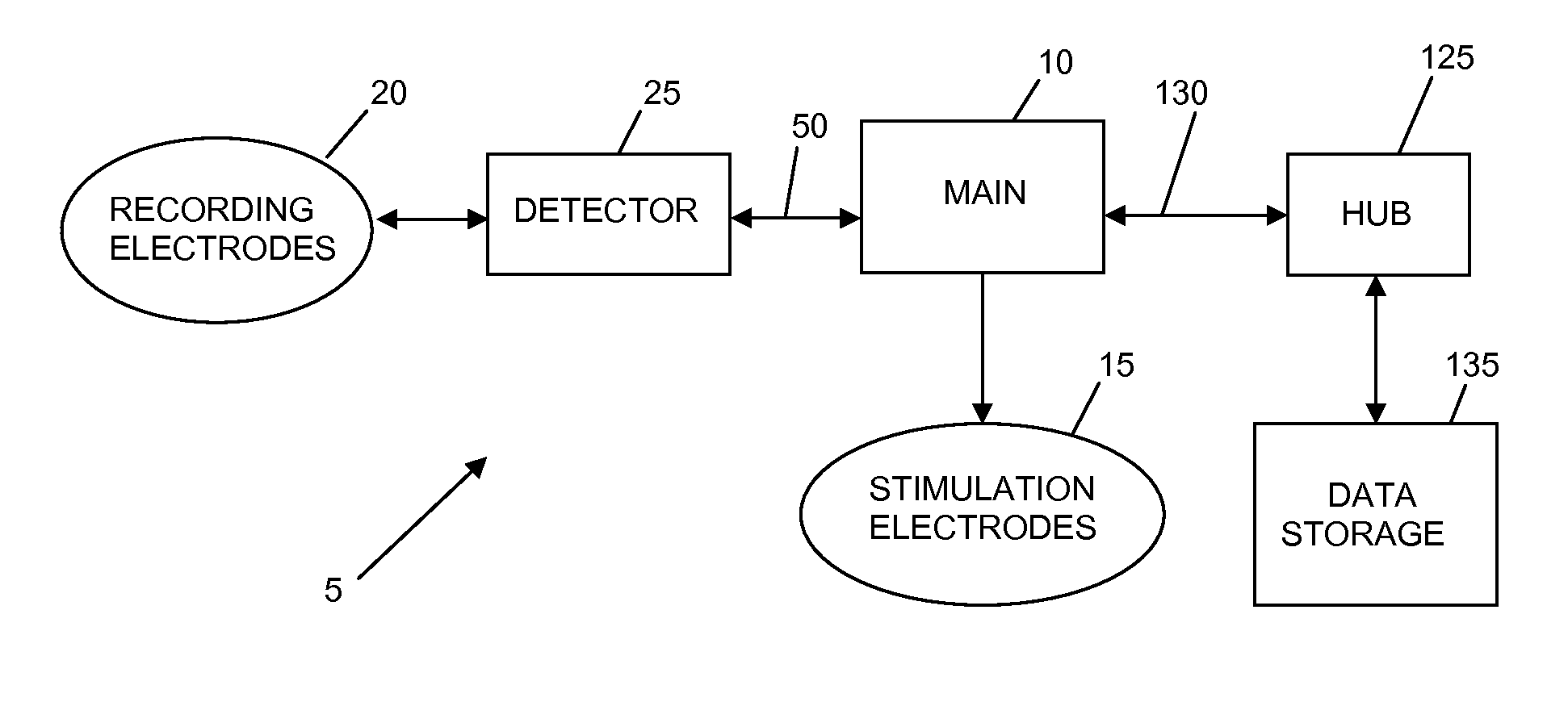
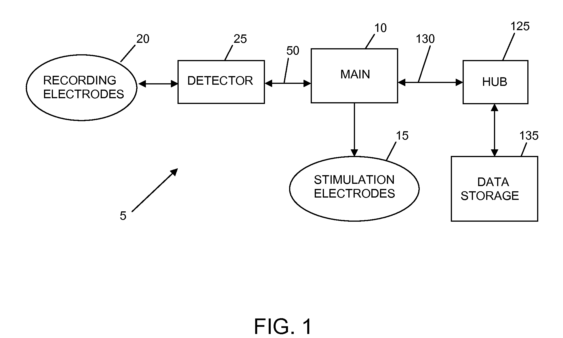
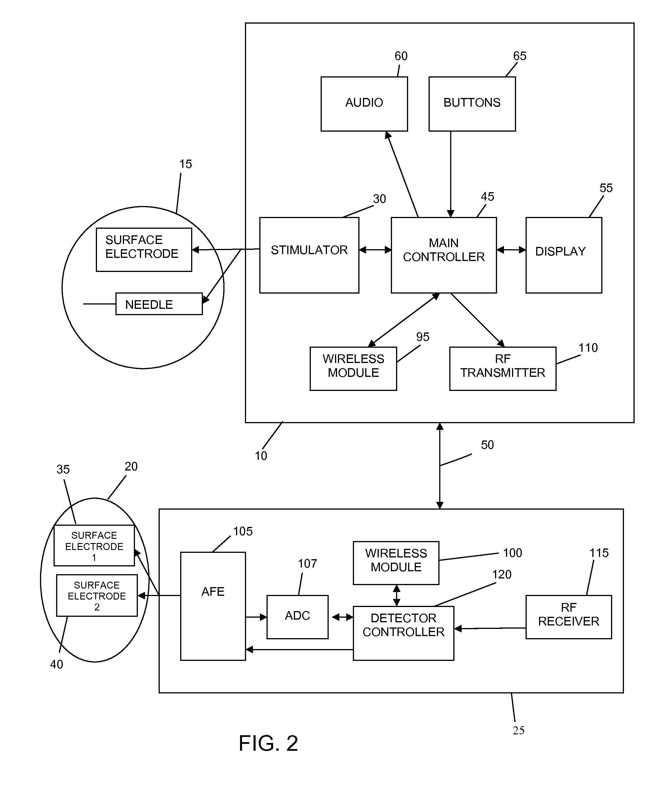
[0077]Looking first at FIG. 1, there is shown a needle localization system 5 for electrically stimulating a nerve of a patient (also sometimes referred to herein as the test subject) using a needle and a surface electrode, detecting the nerve response, and localizing the needle to the nerve based upon the characteristics of the detected nerve responses. In accordance with the present invention, the nerve responses detected by monitoring the muscle innervated by the nerve (in the case of a motor nerve) or by monitoring another portion of the nerve (in the case of a sensory nerve) so as to provide a nerve response trace, and then detecting variations in the nerve response trace which are indicative of nerve response (e.g., variations in the amplitude of the trace).

[0078]More particularly, needle localization system 5 generally comprises a main unit 10 for stimulating a nerve through st...


PUM


Abstract

A method for localizing a needle to a nerve, the method comprising:using the needle to electrically stimulate the nerve, with a known current intensity, so as to evoke a nerve response;detecting the nerve response;analyzing the detected nerve response so as to identify at least one attribute of the same; andconfirming that the needle is in the immediate proximity of the nerve based upon known current intensity and at least one identified attribute of the detected nerve response.

Description

REFERENCE TO PENDING PRIOR PATENT APPLICATIONS[0001]This patent application is:[0002](i) a continuation-in-part of pending prior U.S. patent application Ser. No. 11 / 801,865, filed May 11, 2007 by Changwang Wu et al. for NON-INVASIVE ACQUISITION OF LARGE NERVE ACTION POTENTIALS (NAPs) WITH CLOSELY SPACED SURFACE ELECTRODES AND REDUCED STIMULUS ARTIFACTS (Attorney's Docket No. NEURO-16);[0003](ii) a continuation-in-part of pending prior U.S. patent application Ser. No. 12 / 002,039, filed Dec. 14, 2007 by Michael Williams et al. for NEUROLOGICAL DIAGNOSTIC AND THERAPEUTIC SYSTEM UTILIZING FUNCTION-SPECIFIC MODULES (Attorney's Docket No. NEURO-22);[0004](iii) a continuation-in-part of pending prior U.S. patent application Ser. No. 12 / 274,759, filed Nov. 20, 2008 by Charles Fendrock et al. for DISPOSABLE NEEDLE ELECTRODE WITH IDENTIFICATION, AND ALTERABLE, CONNECTOR INTERFACE (Attorney's Docket No. NEURO-28); and[0005](iv) claims benefit of pending prior U.S. Provisional Patent Applicatio...

Claims


Application Information

Patent Timeline
IPC IPC(8): A61B5/05
CPCA61B5/04001A61N1/0456A61N1/37211A61N1/08A61N1/36021A61N1/0502A61B5/4041A61B5/24A61B5/388
Inventor WU, CHANGWANGGOZANI, SHAIKONG, XUAN
Owner NEUROMETRIX
Learn More