

Electric motor
a technology of electric motors and motors, applied in the direction of dynamo-electric components, ac commutators, magnetic circuit shapes/forms/construction, etc., can solve the problems of material waste, stator core, and uneven magnetic field across the poles
- Summary
- Abstract
- Description
- Claims
- Application Information
AI Technical Summary
Benefits of technology
Problems solved by technology
Method used
Image

Examples
first embodiment
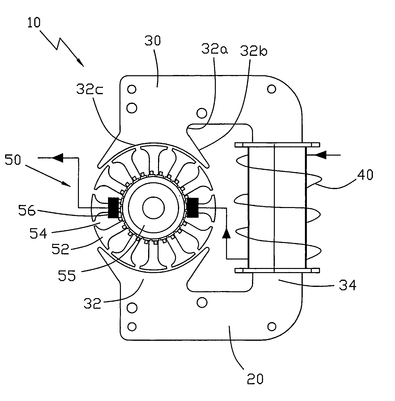
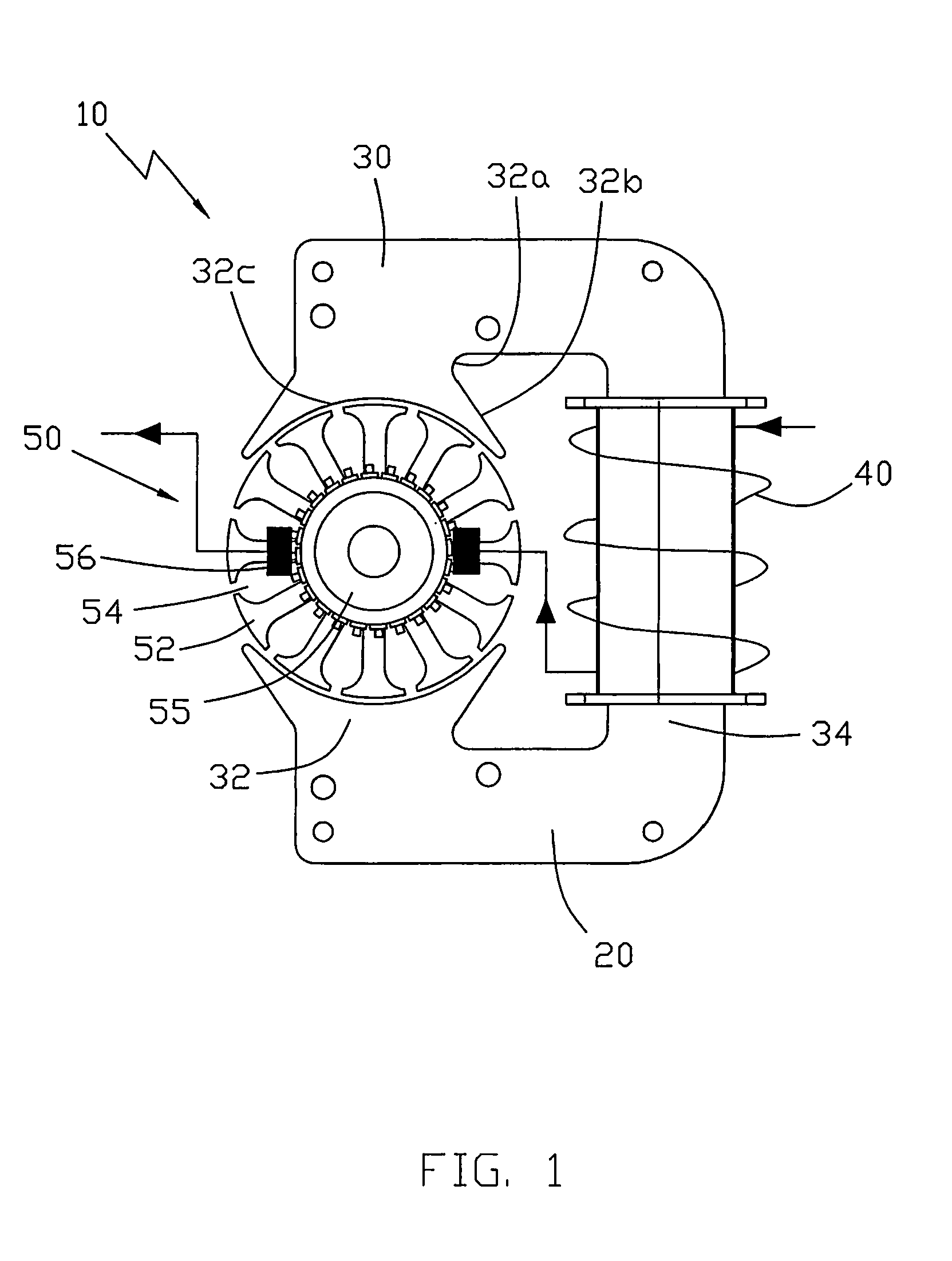
[0020]As shown in FIG. 1, the present invention provides a universal motor 10 comprising a stator 20 and a rotor 50. The stator 20 comprises a stator core 30 and a stator winding 40. The stator core 30 comprises two salient stator poles 32 facing the rotor 50 there between, and a U-shaped yoke 34 connecting the two stator poles 32. The yoke 34 has a base portion and two arm portions extending from the base portion and extending about the rotor. Each salient stator pole 32 comprises a comparatively narrow neck portion 32a, and a pole shoe extending from the neck portion 32a. The pole shoe has an arcuate pole face 32c facing the rotor 50 and has two circumferentially spaced ends 32b which extend circumferentially beyond the neck portion. The rotor 50 is located in the spaced between the pole faces of the two poles 32. The pole face 32c completely extends beyond the edge of the yoke 34 in the radial direction of the rotor 50. The width of the neck portion 32a is greater than the width ...
second embodiment
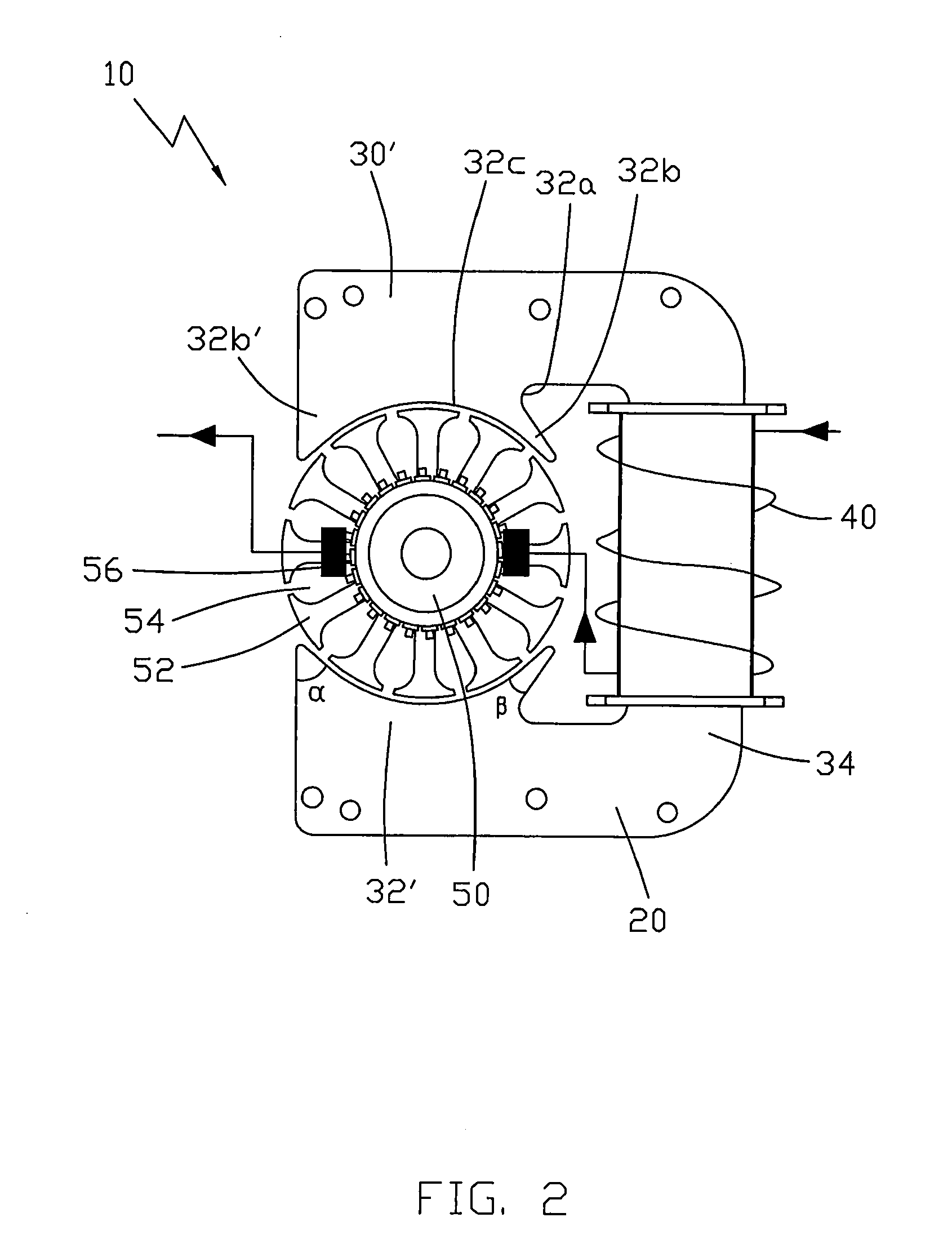
[0022]Another embodiment of the present invention, as shown in FIG. 2, provides a universal motor 10′ which is similar to the universal motor 10 of FIG. 1. The main difference between the motors 10 and 10′ is that in the universal motor 10′, the angle α formed by a first end of the pole shoe 32b′ remote from the stator winding 40 in the plane perpendicular to the rotational axis of the rotor 50, is greater than the angle β formed by the second end of the pole shoe 32b adjacent to the stator winding 40 in the same plane. Usually, the reluctance of the magnetic path through the pole shoes close to the stator winding is less than that of the path through the pole shoes further away from the stator winding, as the length of the path is shorter. In the second embodiment, the design that the angle α formed by the first end of the pole shoe 32b′ remote from the stator winding 40 is greater than the angle β formed by the second end of the pole shoe 32b adjacent to the stator winding 40 will...
third embodiment
[0025]In the third embodiment, the two poles 32′ of the stator 20 are non-salient poles when no magnetic flux barriers are formed therein. At least a part of pole face 32a of the stator poles 32′ extend into the ends of the arms of the yoke in the radial direction of the rotor. However, with the provision of the magnetic flux barriers 38, the poles 32′ of the stator 20 function as salient poles.
[0026]In the present invention, salient poles in which the pole face completely extends beyond the ends of the yoke in the radial direction of the rotor such as in the first and second embodiments and non-salient poles functioning as salient poles such as in the third embodiment are all known as equivalent salient poles.
[0027]Preferably, the magnetic flux barriers 38 are through holes. The holes may have a circular, elliptical or other suitable cross section. Preferably, the line connecting the edges of the holes of the flux barriers 38, at the closest point to the pole face 32a is coaxial or...
PUM
 Abstract
Description
Claims
Application Information