Rack and pinion refrigerator storage system

a refrigerator and rack technology, applied in the field of refrigerator storage systems, can solve the problems of ineffective system, inability to create an effective seal, difficulty in ensuring and inability to ensure the same placement or near identical placement relative to the refrigerator cabinet face of left and right drawer components

Active Publication Date: 2009-12-10
WHIRLPOOL CORP
View PDF27 Cites 67 Cited by
  • Summary
  • Abstract
  • Description
  • Claims
  • Application Information

AI Technical Summary

Benefits of technology

[0011]In use, the gear covers are partially attached to the respective retainers and the gear wheels are connected by the axle extending through the gear covers and retainers. The storage basket can then be angled such that first and second retaining bars extending from the basket are hooked under tabs extending from the respective supports. First and second retaining bars extending from the bottom of the storage basket fit within a channel defined by the top walls of telescoping slide assemblies and the supports. The gear wheels are then aligned upon rack gears located on respective supports, and the gear covers are snapped into full engagement with the retainers. With this configuration, the gear wheels are rotatably connected to the storage basket and have equal rotational and linear motion along the rack gears when the storage basket is slid into and out of the refrigerator compartment. In this fully assembled configuration, the gear covers lock the gear assembly to the basket, and the tabs engage the retaining bar to prevent the storage basket from being removed from the refrigerator compartment. Optionally, a removable basket divider may be utilized to partition the storage basket into multiple storage units.
[0012]Additional objects, features and advantages of the present invention will become more readily apparent from the following detailed description of a preferred embodiment when taken in conjunction with the drawings wherein like reference numerals refer to corresponding parts in the several views.

Problems solved by technology

Unfortunately, these slides extend at different rates when the large drawer is opened and closed, particularly when the horizontal force, i.e., the consumer pushing or pulling on the drawer or basket, is not centered.
A further problem with presently available systems is that it is difficult to ensure identical, or near identical, placement relative to the refrigerator cabinet face of left and right drawer components.
Without proper component placement, the drawer may not completely close, resulting in the failure to create an effective seal which allows air to permeate into or out of the drawer.
The inability of the drawer to completely close creates an inefficient system, making it difficult to regulate temperatures, humidity, and other factors within the drawer.
Though such systems prevent wobble, these attempts have not prevented the drawer from assuming a racked condition resulting from the opening force or food load center of mass occurring significantly away from the drawer's center.
Likewise, no simple means of aligning, during initial assembly, left and right gear wheels to associated rack gears of a drawer employing a rack and pinion system has been available.
As a result, if the drawer, and in particular the rack and pinion system, becomes misaligned, no means exists for the correction of the misaligned drawer apart from complete disassembly and removal of the drawer from the cabinet.
This task becomes particularly difficult when the drawer is filled with food or other stored items.
Due to the removal and reinsertion of the drawer, as well as the inward and outward movement required to reset the misaligned drawer, these systems do not provide much improvement, as the drawer must still be removed, and a significant amount of effort is required of the drawer operator to realign the drawer.
The use of a single rack and pinion, however, does not provide a stable means of securing the drawer, as a minor amount of lateral force or movement of the drawer will cause misalignment of the drawer, as well as the rack and pinion, causing wobble, or resulting in jamming of the drawer.

Method used


Image

  • Rack and pinion refrigerator storage system
  • Rack and pinion refrigerator storage system
  • Rack and pinion refrigerator storage system

Examples


Embodiment Construction

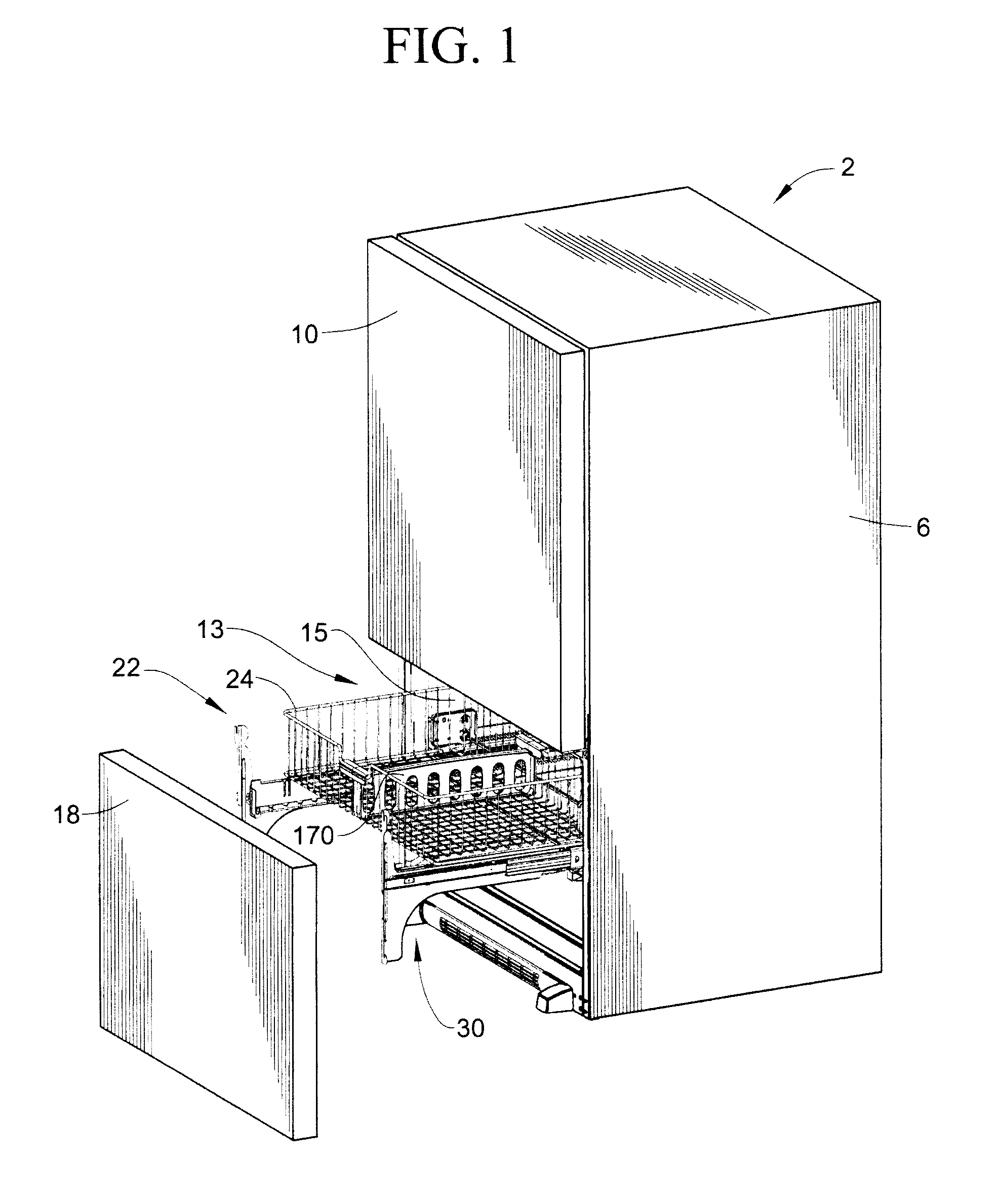
[0020]With initial reference to FIG. 1, a refrigerator incorporating the invention is generally indicated at 2. Refrigerator 2 includes a cabinet shell 6 to which is attached a fresh food compartment door 10. At this point, it should be readily recognized that refrigerator 2 constitutes a bottom mount style refrigerator wherein fresh food compartment door 10 is adapted to seal off an upper fresh food compartment defined within cabinet shell 6. In a manner known in the art, fresh food compartment door 10 is preferably, pivotally mounted about a vertical axis to cabinet shell 6 through upper and lower hinges (not shown). Refrigerator 2 also includes a lower freezer compartment 13 which is defined by a liner having opposing sidewalls 15. Freezer compartment 13 is adapted to be sealed by means of a freezer door 18. In accordance with the present invention, freezer door 18 is adapted to slide towards and away from cabinet shell 6, in part, through the use of a stabilizer system indicated...


PUM


Abstract

A rack and pinion storage system for use in a refrigerator compartment defined by a liner includes a pair of supports attached to opposing sidewalls of the liner. First and second gear covers snap-fittingly connect first and second gear wheels to respective first and second mounting brackets extending from a storage basket, such that the gear wheels are rotatably connected to the storage basket and have equal rotational and linear motion along the respective supports. Retaining bars extending from the storage basket are held within channels defined between the bottom walls of the supports and top walls of opposing telescoping slide assemblies used to movably support a door of the compartment. Tabs extending from the supports limit the sliding movement of the storage basket. A removable divider connects to the storage basket, sectioning the basket into multiple storage compartments.

Description

BACKGROUND OF THE INVENTION[0001]1. Field of the Invention[0002]The present invention relates to the art of refrigerators and, more specifically, to a rack and pinion storage system for a drawer assembly of a refrigerator.[0003]2. Discussion of the Related Art[0004]Pullout drawers in refrigerator cabinets, and in particular bottom mounted freezer drawers in which the freezer compartment is located at the bottom of the refrigerator while the fresh food compartment is located at the top of the refrigerator, are often used to increase versatility of storing a wide range of food items, and increasing the accessibility of items stored in the lower portion of the refrigerator cabinet. To this end, in commercially available bottom mounted freezers, a large freezer drawer or basket is provided in connection with or in place of a hinged or swinging door. These bottom mounted freezer drawers are typically mounted on slides or glides fastened to the sidewalls of the inner liner of the refriger...

Claims


Application Information

Patent Timeline
Patent Type & Authority Applications(United States)
IPC IPC(8): A47B96/04
CPCF25D25/025F25D25/022
Inventor ROTTER, CHAD J.OTT, LESTER J.HERNDON, STEVEN G.
Owner WHIRLPOOL CORP
Why Eureka
Try Eureka