Apparatus and method for holding a rotatable eddy-current magnetic probe, and for rotating the probe around a boundary

a magnetic probe and rotatable technology, applied in the field of remote field eddycurrent non-destructive testing, can solve problems such as changes to observed rfec signals, and achieve the effects of reducing signal changes, minimizing detection, and reducing signal changes

Active Publication Date: 2009-12-10
INNOVATIVE MATERIALS TESTING TECH
View PDF3 Cites 17 Cited by
  • Summary
  • Abstract
  • Description
  • Claims
  • Application Information

AI Technical Summary

Benefits of technology

[0006]In some embodiments, the invention provides an apparatus that includes a magnetically shielded excitation unit that generates an alternating excitation magnetic signal; and one or more magnetically shielded sensors that are positioned adjacent the excitation unit and that are configured to detect a remote-field eddy-current signal due to the excitation magnetic signal, wherein the apparatus is configured to scan a surface (e.g., of a metal plate) having a structure (e.g., a joint, or a fastener such as a rivet) in order to detect anomalous signal changes around the structure in a manner that reduces signal changes due to a boundary between the structure and the surface.
[0007]In some embodiments, the invention provides a method that includes forcing an alternating excitation magnetic field into a surface, detecting a remote-field eddy-current signal resulting from the alternating excitation magnetic field at each of a plurality of positions on the surface surrounding a structure on the surface in a manner that reduces signal changes due to a boundary between the structure and the surface; and analyzing the detected signal from the plurality of positions to determine whether the surface contains an anomaly next to the structure.
[0008]In some embodiments, the invention provides a method that includes providing an apparatus comprising an excitation unit and one or more sensors next to the excitation unit; shielding the excitation unit and the one or more sensors to minimize detection of signals other than remote-field eddy-current signals by the one or more sensors; and configuring the excitation unit and the one or more sensors to detect anomalous signal changes around a structure in a surface in a manner that reduces signal changes due to a boundary between the structure and the surface.
[0009]In some embodiments, the invention provides an apparatus that includes means for forcing an alternating excitation magnetic field into a surface; means for detecting a remote-field eddy-current signal resulting from the alternating excitation magnetic field at each of a plurality of positions on the surface surrounding a structure in the surface in a manner that reduces signal changes due to a boundary between the structure and the surface; and means for analyzing the detected signal from the plurality of positions to determine whether the surface contains an anomaly next to the structure.

Problems solved by technology

Cracks, discontinuities, holes, and changes in the material content all affect the eddy current flow within an object and also affect the magnetic field external to the object.
Generally, the drive-sensor separation for an RFEC probe is greater than that of a non-RFEC probe; however, geometrical separation of the two coils is not a defining characteristic that distinguishes a “remote field” from a “near field” probe.
Changes to an observed RFEC signal can be caused by undesirable anomalies, such as cracks, voids, internal or surface corrosion, embedded foreign objects, alloy-composition changes, etc., as well as by expected inherent features of the object being examined, such as joints and fasteners.

Method used


Image

  • Apparatus and method for holding a rotatable eddy-current magnetic probe, and for rotating the probe around a boundary
  • Apparatus and method for holding a rotatable eddy-current magnetic probe, and for rotating the probe around a boundary
  • Apparatus and method for holding a rotatable eddy-current magnetic probe, and for rotating the probe around a boundary

Examples


Embodiment Construction

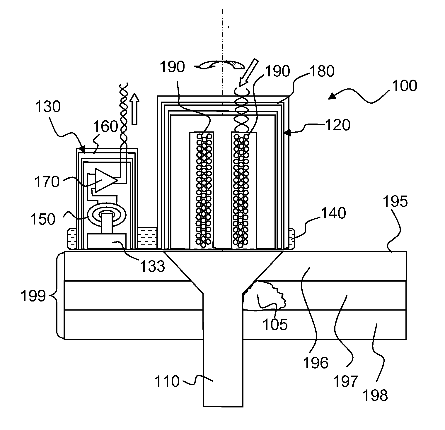
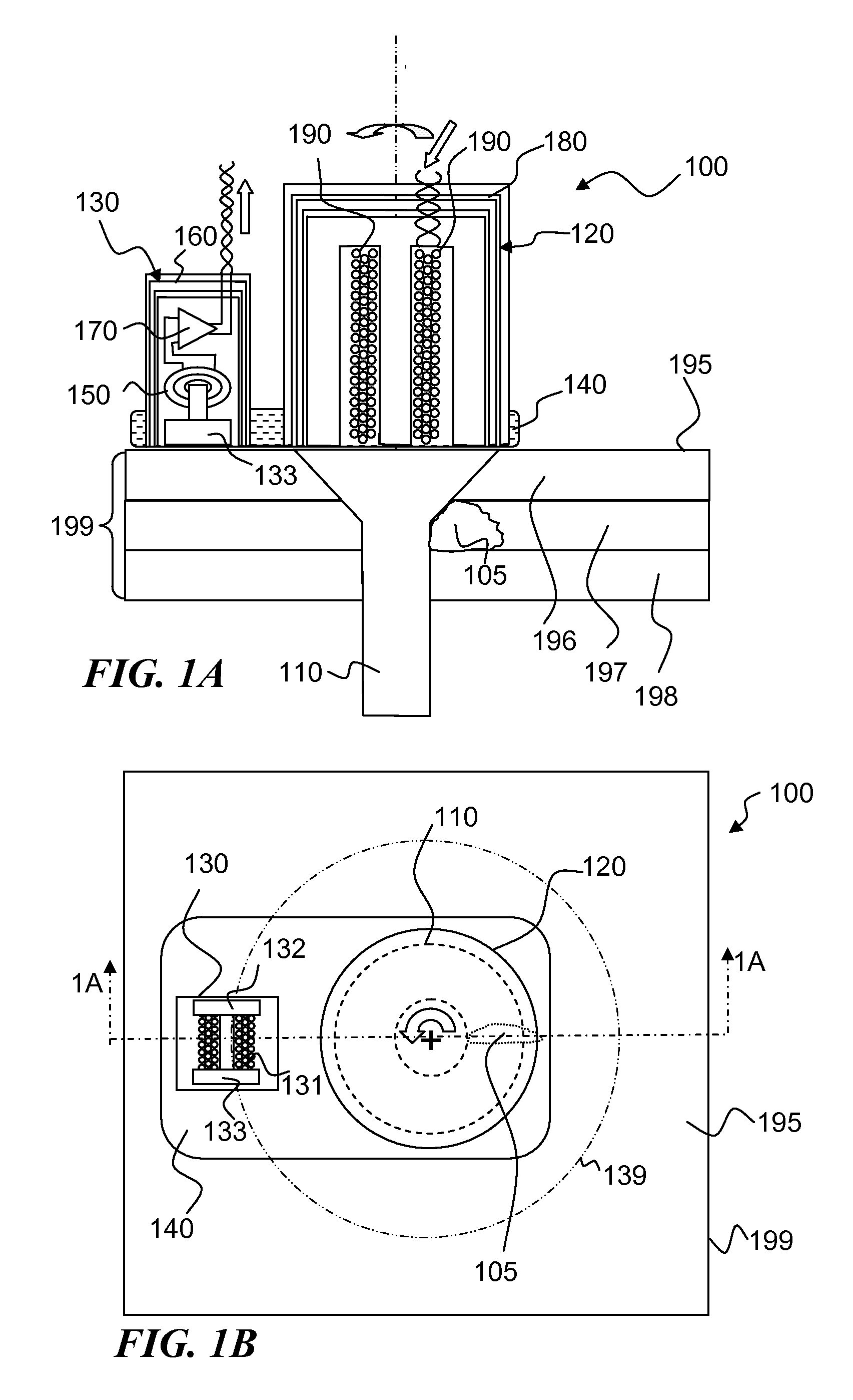
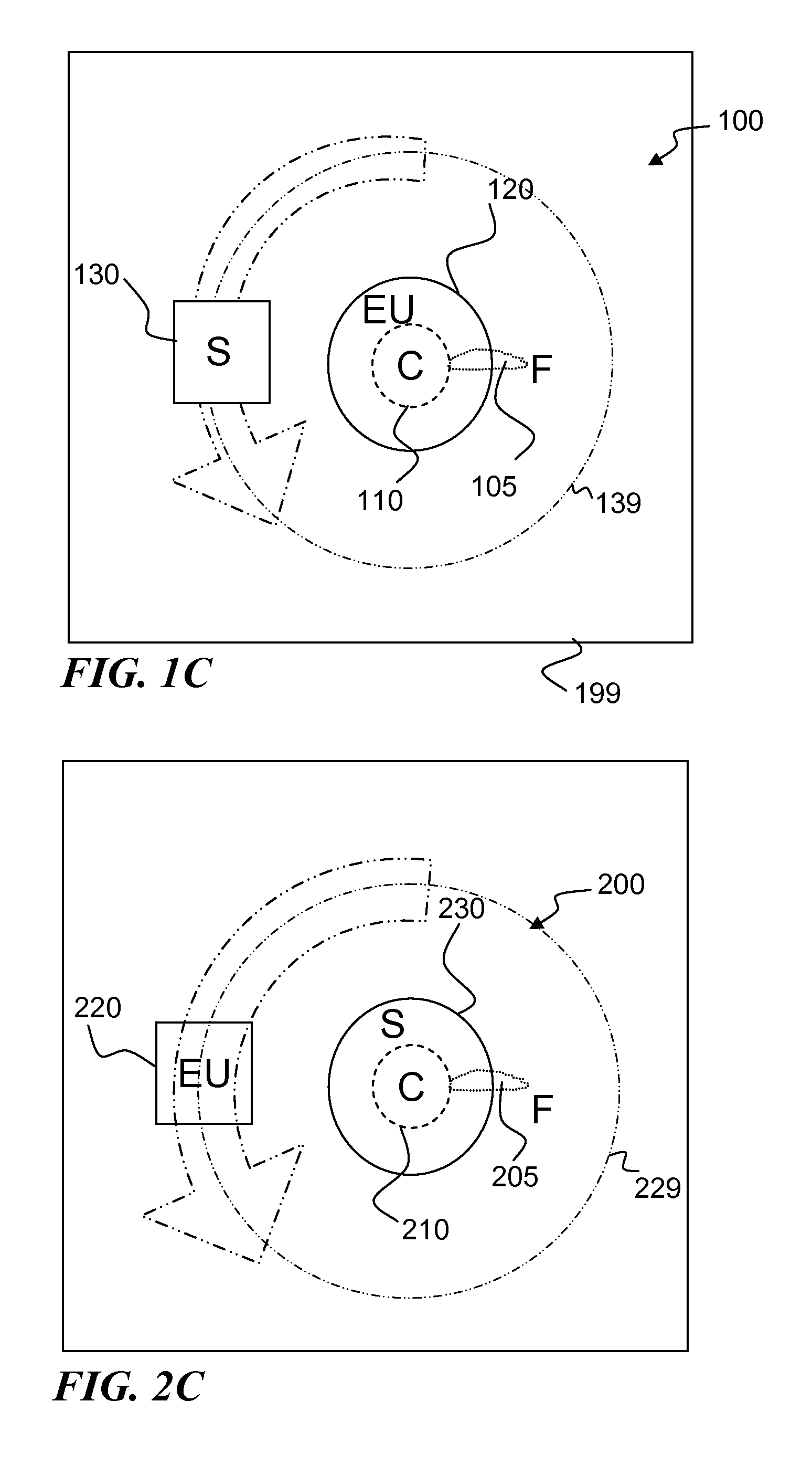
[0040]The invention provides methods and apparatuses that can be used to scan an object for an anomaly. Generally, an apparatus of the invention is placed onto a surface of the object to be scanned so that an excitation unit that is a part of the apparatus is positioned to force an alternating excitation magnetic field into the object. The magnetic field produces near-field eddy currents that can be detected in close proximity to the excitation unit and remote-field eddy-currents that can be detected further away from the excitation unit relative to the near-field eddy-currents. A sensor that is part of the apparatus is positioned to detect the remote-field eddy-currents. Detection of the remote-field eddy-currents can be improved by shielding the sensor from the near-field eddy-currents.

[0041]The amplitude and intensity of the remote-field eddy-current will stay substantially constant at positions that are substantially radially equidistant from the excitation unit if the magnetic ...


PUM

PropertyMeasurementUnit
frequencyaaaaaaaaaa
frequenciesaaaaaaaaaa

Abstract

An RFEC excitation unit and sensor apparatus and method that facilitate detection of cracks or other anomalies within or under a surface and immediately next to an expected structure (such as a rivet) that would otherwise cause a signal change preventing detection of the cracks. In some embodiments, the apparatus includes actuators and control that move the apparatus and analyze sensed RFEC signals to determine the location of the rivet, and then to rotate (mechanically or electronically) the sensed signal and / or excitation signal to maintain a constant relationship to the edge of the rivet in order that signals from the rivet edge are suppressed and signals from the cracks are detected. In some embodiments, the excitation unit is maintained at the center of the rivet surface, and the sensor is moved around the rivet in a circle centered on the rivet.

Description

REFERENCE TO RELATED APPLICATIONS[0001]This application is a divisional application of U.S. patent application Ser. No. 11 / 114,507 filed on Apr. 25, 2005 and titled “APPARATUS AND METHOD FOR EDDY-CURRENT MAGNETIC SCANNING A SURFACE TO DETECT SUB-SURFACE CRACKS AROUND A BOUNDARY” which issued as U.S. Pat. No. 7,301,335 on Nov. 27, 2007 and which is incorporated herein by reference in its entirety. U.S. patent application Ser. No. 11 / 114,507 claimed benefit of U.S. Provisional Patent Application Ser. No. 60 / 564,906, entitled “METHOD AND AUTO-CENTERING PROBE FOR ENHANCED DETECTION OF SUB-SURFACE CRACKS AROUND RIVETS OR THE LIKE” filed Apr. 23, 2004, which is incorporated herein by reference in its entirety.FIELD OF THE INVENTION[0002]The present invention relates to remote-field eddy-current non-destructive testing, and more particularly, to probes that reject circumferential eddy-current waves or noise around a rivet or the like in order to better detect radial defects, and particular...

Claims


Application Information

Patent Timeline
Patent Type & Authority Applications(United States)
IPC IPC(8): G01N27/82
CPCG01N27/82
Inventor SUN, YUSHIOUYANG, TIANHE
Owner INNOVATIVE MATERIALS TESTING TECH
Why Eureka
Try Eureka