
Shared virtual network interface

Active Publication Date: 2009-12-10
ORACLE INT CORP
View PDF6 Cites 50 Cited by
  • Summary
  • Abstract
  • Description
  • Claims
  • Application Information

AI Technical Summary

Benefits of technology

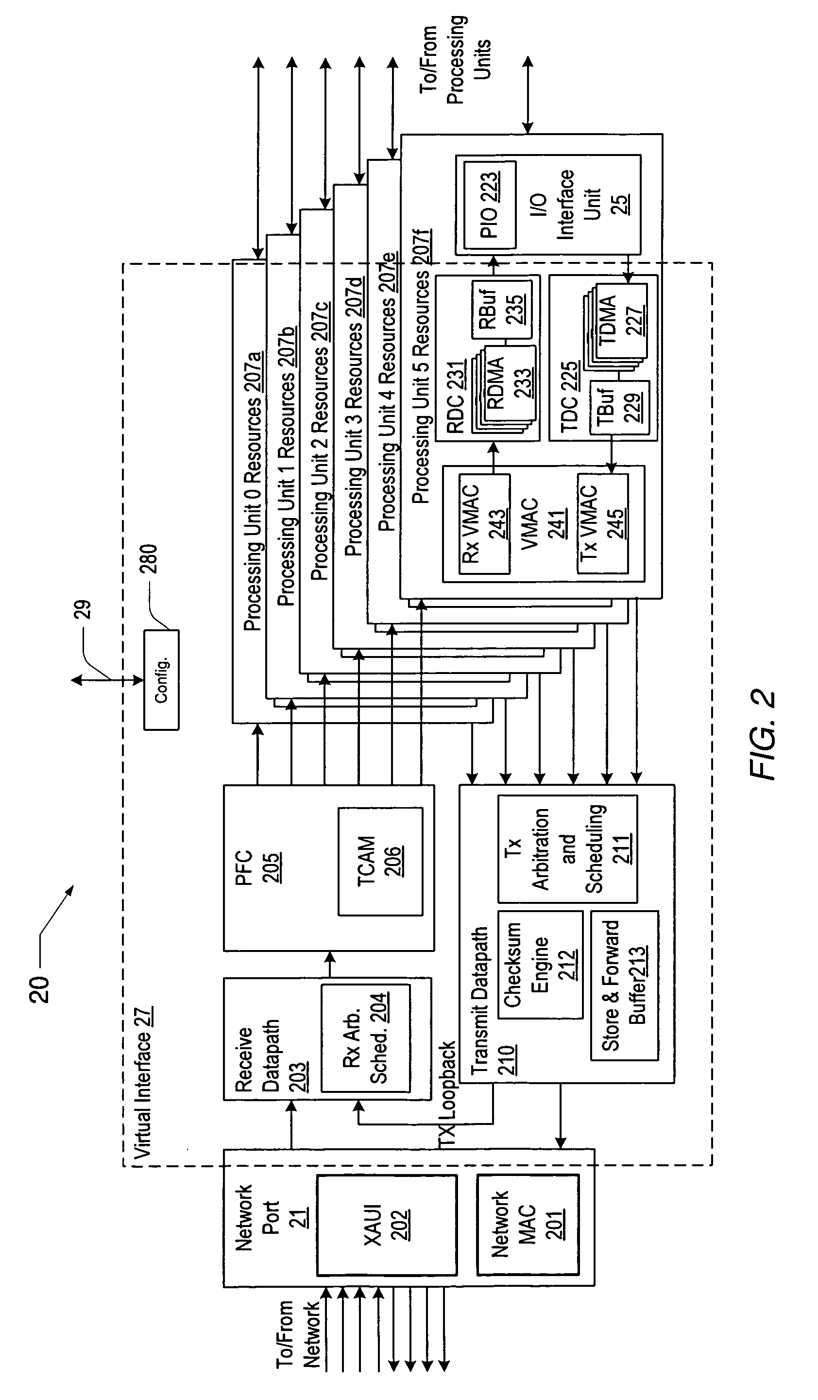
[0006]Various embodiments of a shared virtual network interface are disclosed. In one embodiment, a system includes one or more processing units coupled to a network interface unit. The network interface unit may include a network port for connection to a network such as an Ethernet network, for example, and a virtual interface that may be configured to distribute an available communication bandwidth of the network port between the one or more processing units. The network port may include a shared media access control (MAC) unit. The virtual interface may be coupled to the network port. The virtual interfac

Problems solved by technology

In addition, the costs associated the networking components may also be high, especially for some of the newer standards such as 10 Gigabit Ethernet (10 GE), for example.
Additional drawbacks associated with large networked systems include the large amount of rack space that must be dedicated to cabling, network port connectors, and the like, and the mechanical issues and mean time between failure (MTBF) for these components.

Method used


Image

  • Shared virtual network interface
  • Shared virtual network interface
  • Shared virtual network interface

Examples


Embodiment Construction

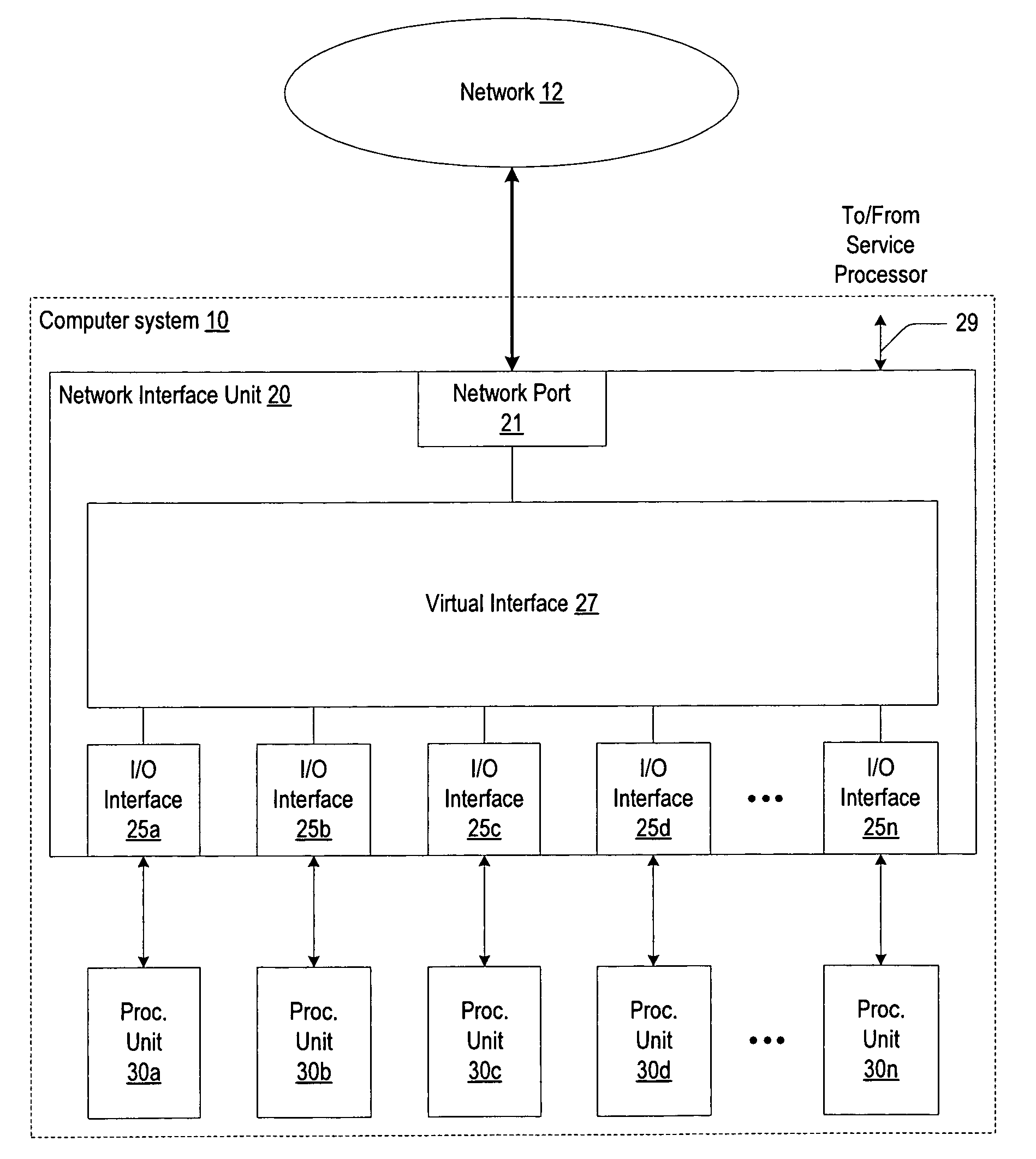
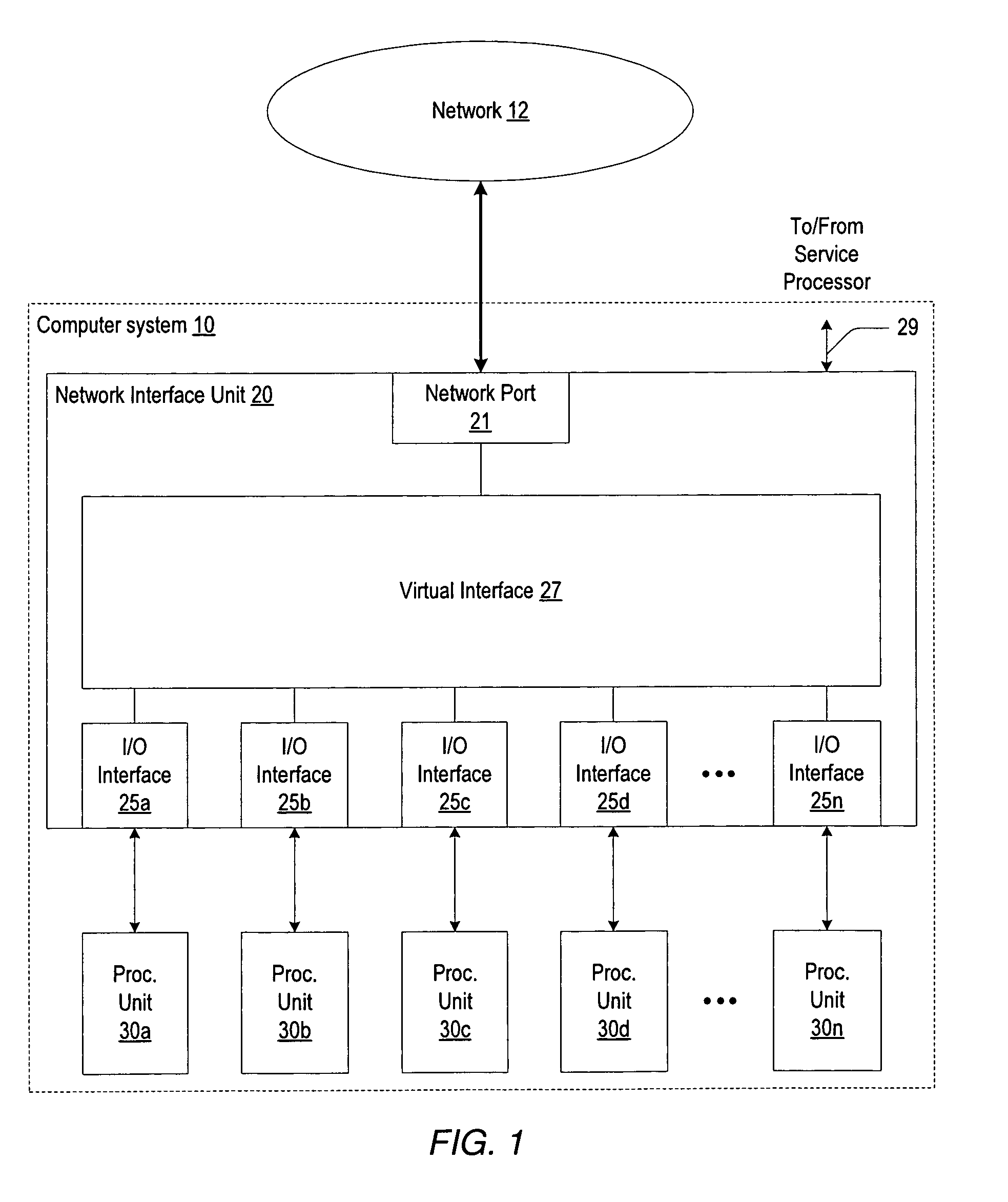
[0012]Turning now to FIG. 1, a block diagram of one embodiment of a computer system connected to a network is shown. Computer system 10 includes a plurality of processing units designated 30a-30n, where n may be representative of any number. As shown, each of the processing units is coupled to a network interface unit 20. The network interface unit 20 is coupled to a network 12. It is noted that components having reference designators with a number and letter may be referenced by just the number where appropriate.

[0013]In one embodiment, each of the processing units 30 may be representative of a processing node such as a blade server, for example, that may include one or more processors or CPUs. However, it is contemplated that in other embodiments, any type of processing node may be used.

[0014]As shown in FIG. 1, the network interface unit 20 includes a network port 21, a virtual interface 27, and a plurality of input / output (I / O) interfaces, designated 25a-25n, where n may be repr...


PUM


Abstract

A system includes one or more processing units coupled to a network interface unit. The network interface unit may include a network port for connection to a network and a virtual interface that may be configured to distribute an available communication bandwidth of the network port between the one or more processing units. The network port may include a shared media access control (MAC) unit. The virtual interface may include a plurality of processing unit resources each associated with a respective one of the one or more processing units. Each of the processing unit resources may include an I / O interface unit coupled to a respective one of the one or more processing units via an I / O interconnect, and an independent programmable virtual MAC unit that is programmably configured by the respective one of the one or more processing units. The virtual interface may also include a receive datapath and a transmit datapath that are coupled between and shared by the plurality of processing unit resources and the network port.

Description

BACKGROUND OF THE INVENTION[0001]1. Field of the Invention[0002]This invention relates to networking systems and, more particularly, to shared network resources.[0003]2. Description of the Related Art[0004]Networked computer systems are typically connected to a network using some type of network interface. The type of interface varies depending on the network protocol. For example, in an Ethernet network, a computer system or processing node may connect to the network using a network interface card (NIC). The NIC may be assigned a unique medium access control (MAC) address that identifies that NIC to all the other computer systems in the world that may be connected to the network. In a conventional system, each processing node may have its own NIC, and thus its own network port.[0005]In computer systems that include a large number of processing nodes such as, for example, server systems that have a large number of blade processing units in each chassis, the component count of the re...

Claims


Application Information

Patent Timeline
IPC IPC(8): H04L12/66
CPCH04L49/9063H04L49/90
Inventor YANG, ANDREW CYU, JAMES J.
Owner ORACLE INT CORP
Learn More