Image forming apparatus

Inactive Publication Date: 2009-12-10
KYOCERA DOCUMENT SOLUTIONS INC
View PDF7 Cites 6 Cited by
  • Summary
  • Abstract
  • Description
  • Claims
  • Application Information

AI Technical Summary

Benefits of technology

[0007]An object of the present invention is to provide an image forming apparatus that is capable of accurately measuring the movement speed of an intermediate transfer belt to be controlled, in order to output an image with no density fluctuation and color registration error by accurately controlling the movement speed of the intermediate transfer belt of the image forming apparatus.

Problems solved by technology

Particularly, in a tandem system image forming apparatus, inconstant movement speed of the intermediate transfer belt causes displacement of the transfer position of a toner image of each color and a color registration error.
However, when the thickness of the intermediate transfer belt is uneven due to a dimension error caused during the production of the intermediate transfer belt, or when a part of the intermediate transfer belt is stretched as a result of time degradation of the intermediate transfer belt, the speed conversion cannot be performed accurately.
Consequently, the conventional methods for detecting the speed of the inner circumferential surface of the intermediate transfer belt lacks in accuracy of measuring and controlling the speed of the intermediate transfer belt.

Method used


Image

  • Image forming apparatus
  • Image forming apparatus
  • Image forming apparatus

Examples


Embodiment Construction

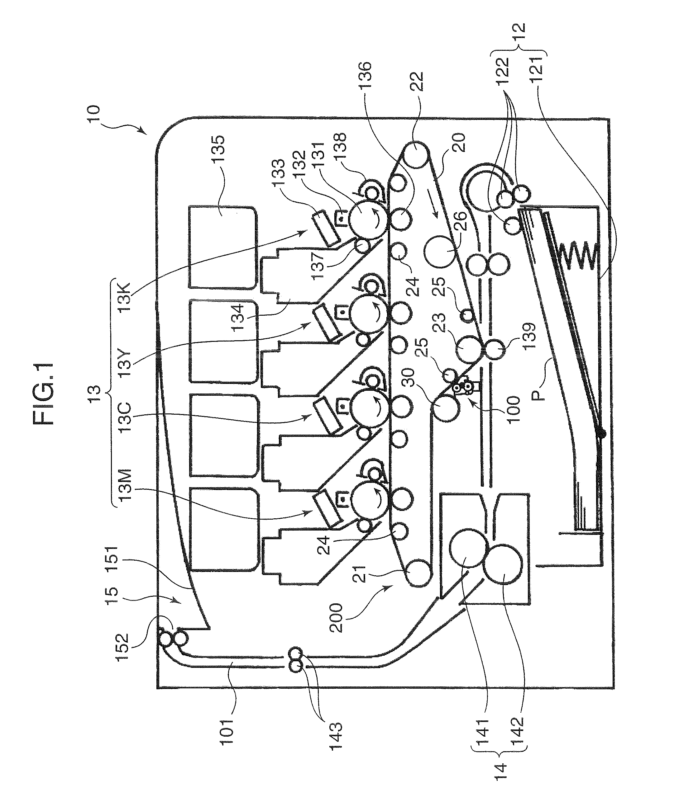
[0015]FIG. 1 is a cross-sectional diagram for explaining an internal structure of an image forming apparatus according to an embodiment of the present invention. In the present embodiment, a printer 10 is adopted as the image forming apparatus. The printer 10 has a paper feed section 12, an image forming section 13, a fixation section 14, and a paper ejection section 15. The paper feed section 12 stores a stack of papers P (recording sheets). The image forming section 13 transfers a toner image corresponding to image information onto each of the papers P conveyed from the paper feed section 12. The fixation section 14 performs fixation processing on the toner image that is transferred onto each sheet of paper P by the image forming section 13. The paper ejection section 15 ejects the paper P subjected to the fixation processing by the fixation section 14.

[0016]The paper feed section 12 has a paper cassette 121 and a pickup roller 122. The paper cassette 121 is insertably mounted in ...


PUM


Abstract

An image forming apparatus has: an image forming section that forms a toner image corresponding to image information; an intermediate transfer belt, which is an endless belt stretched between a plurality of rollers and traveling between the plurality of rollers, the toner image being transferred to a surface thereof or a recording sheet placed on the surface thereof; a driving roller, which is one of the plurality of rollers and drives the intermediate transfer belt; a bending roller, which touches an outer circumferential surface of the intermediate transfer belt and presses and bends the intermediate transfer belt in an inner circumferential direction; and a speed detecting part which detects a movement speed of an outer circumference of the intermediate transfer belt by measuring a rotational speed of the bending roller.

Description

BACKGROUND OF THE INVENTION[0001]1. Field of the Invention[0002]The present invention relates to an image forming apparatus that has an intermediate transfer belt.[0003]2. Description of the Related Art[0004]An image forming apparatus, such as a laser printer and a copy machine, which employs a xerography, has rotating members such as a photosensitive drum, a transfer roller, and an intermediate transfer belt. These rotating members are used for outputting a toner image onto a recording sheet through an electrostatic latent image formation process. It is necessary to control these rotating members accurately, in order to obtain an output result without causing a density fluctuation and image displacement. Especially because the toner image which is output onto the recording sheet is transferred to the intermediate transfer belt, the speed of movement of the intermediate transfer belt needs to be measured accurately and controlled constantly. Particularly, in a tandem system image fo...

Claims


Application Information

Patent Timeline
IPC IPC(8): G03G15/01
CPCG03G15/1605G03G2215/1623G03G2215/0196G03G15/1615
Inventor INOUE, MUTSUMI
Owner KYOCERA DOCUMENT SOLUTIONS INC
Why Eureka
Try Eureka