Median Barrier Cable Termination

a barrier cable and cable termination technology, applied in the field of cable terminations, can solve the problems of reducing the tension of the cable, corrosion inside the anchorage, and the design of the cable termination has not been without challenges

Active Publication Date: 2009-12-10
PRECISION HAYES INT INC
View PDF47 Cites 16 Cited by
  • Summary
  • Abstract
  • Description
  • Claims
  • Application Information

AI Technical Summary

Problems solved by technology

Designing these cable terminations has not been without challenges.
Another problem with cable terminations of this type is corrosion inside the anchor.
For example, corrosion can occur between t

Method used


Image

  • Median Barrier Cable Termination
  • Median Barrier Cable Termination
  • Median Barrier Cable Termination

Examples


Embodiment Construction

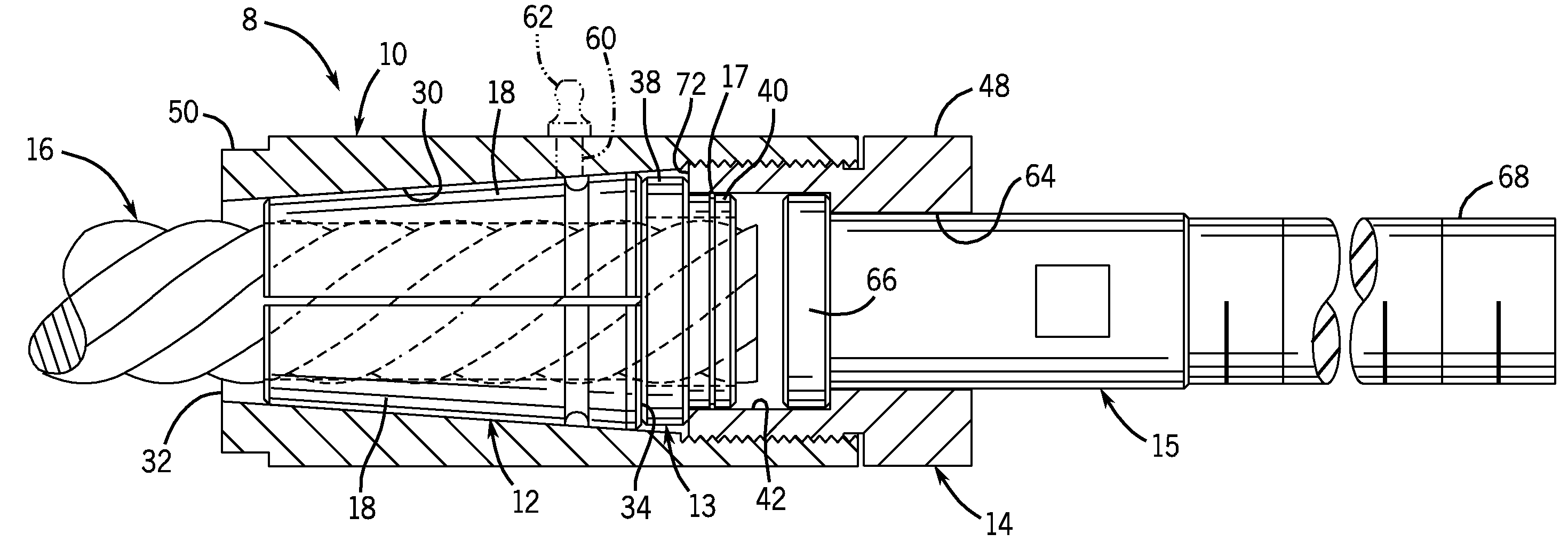
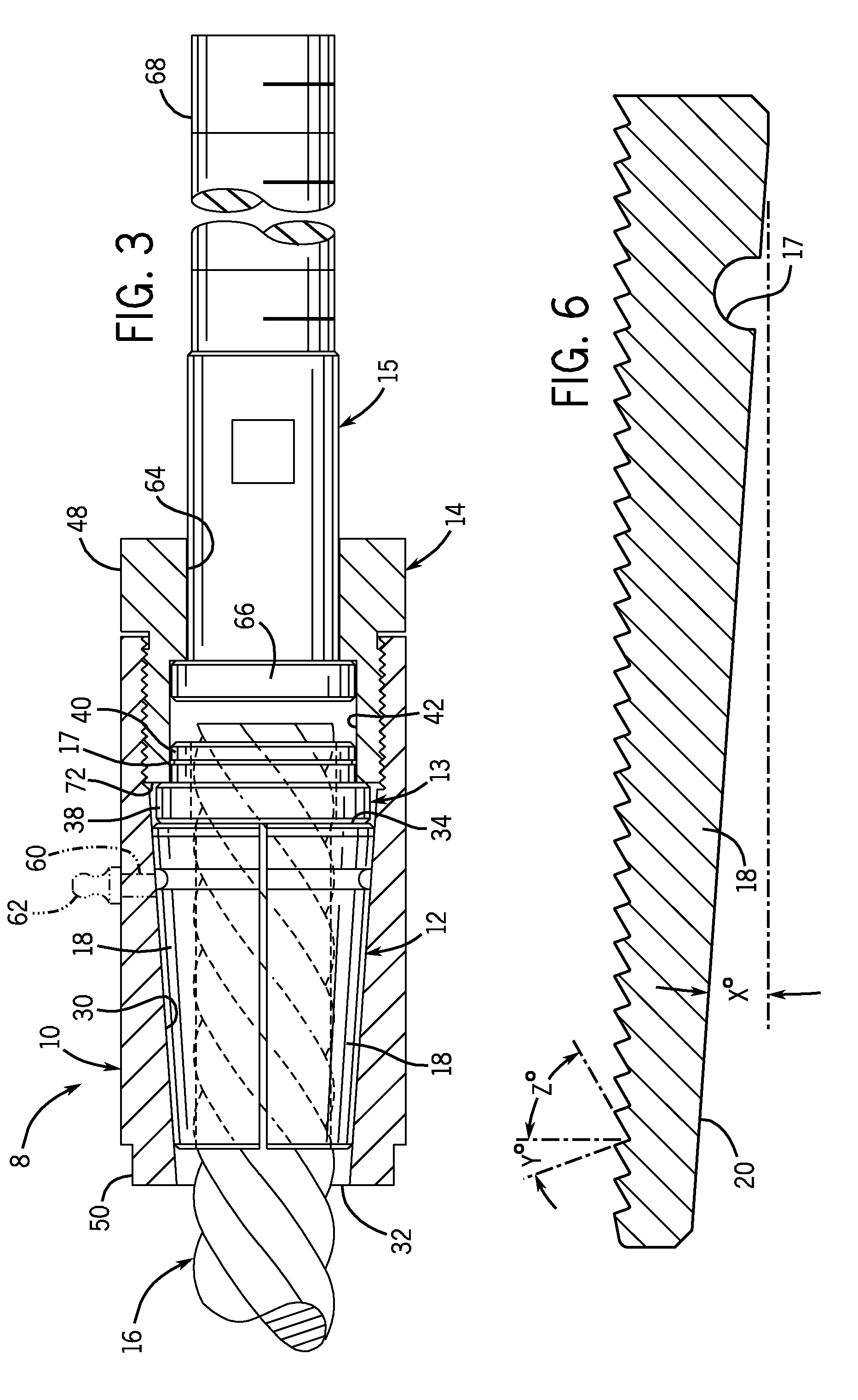
[0026]Referring to FIG. 3, a termination 8 of the invention has a body 10 containing a wedge gripper 12 having a larger diameter end 34 abutting a washer 13 that is pressed against the wedge gripper 12 by a threaded cap 14 that is screwed into the body 10. A stem 15 extends through a hole 64 in the cap 14 and is trapped inside the body 10 and a median barrier cable 16 is trapped by jaw sections 18 of the wedge gripper 12.

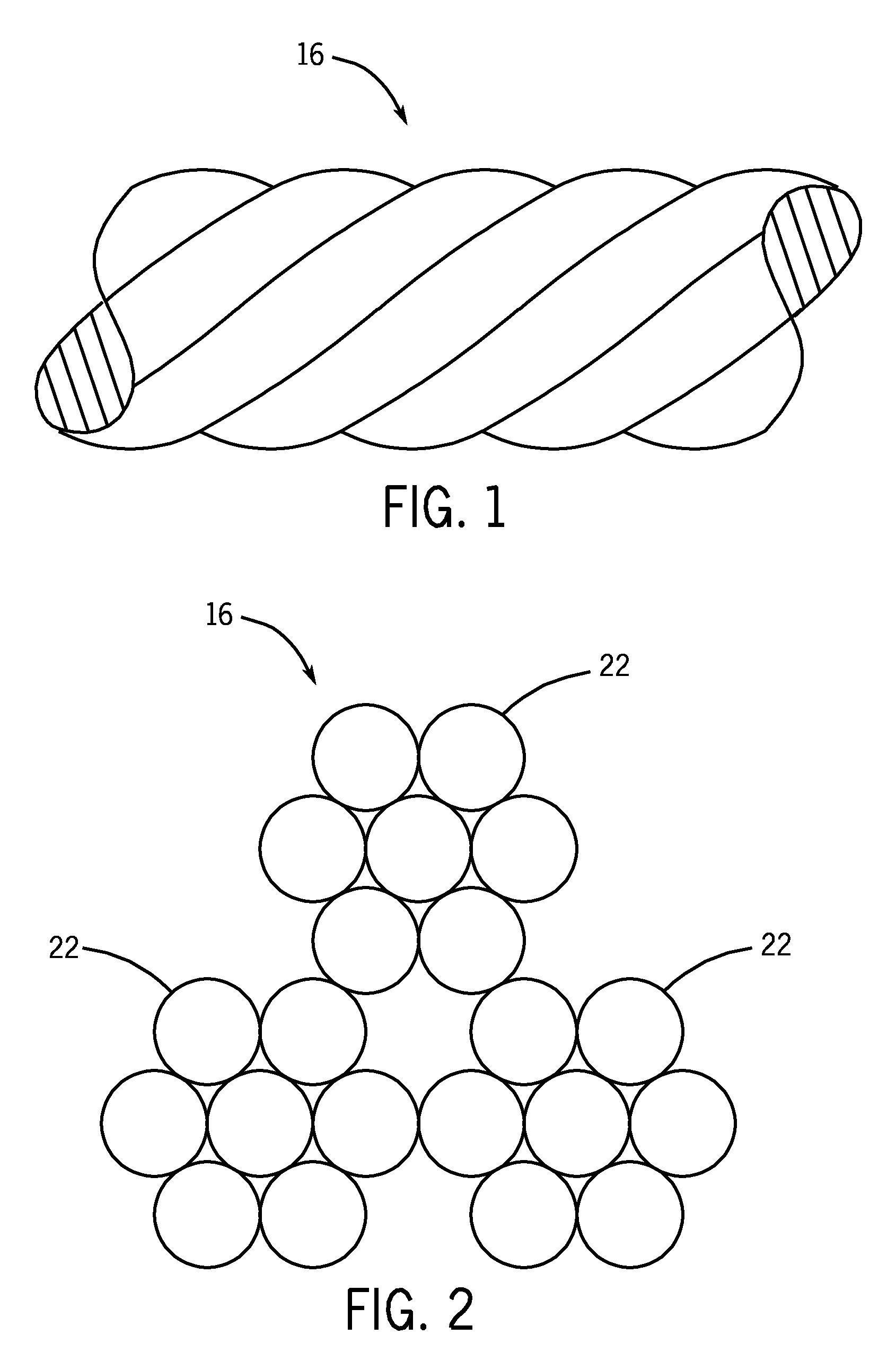
[0027]Referring to FIGS. 4, 5, and 6, the wedge gripper 12 has an outer surface 20 that tapers and, in the example embodiment, is formed by machining a piece of suitable metal, for example tool steel or other steel, to that shape and then drilling a hole in it and tapping the hole so that the hole has teeth, as shown in FIG. 6, that serve to grip the cable 16. The cable 16 has a nominal effective diameter of 19 mm (¾ inches), even though the cross-sectional profile of it as shown in FIG. 2 is not round. However, the circle defined by the outer points of the lobes 22...


PUM

PropertyMeasurementUnit
Angleaaaaaaaaaa
Lengthaaaaaaaaaa
Forceaaaaaaaaaa

Abstract

A cable termination and method of terminating a median barrier cable is described. In one form, the cable termination comprises a tubular body with an opening into which an end of the median barrier cable is inserted. A wedge gripper includes three sections for gripping the end of the median barrier cable within the tubular body. The wedge gripper has a tapering outer surface that mates with a tapered inner surface of the tubular body and has a toothed inner diameter. A threaded cap is screwed to an end of the tubular body opposite from the cable opening, such that the threaded cap forces the tapering outer surface of the wedge gripper axially against the tapered inner surface of the tubular body to force the toothed inner diameter of the wedge gripper to contract against three lobes of the median barrier cable to grip the median barrier cable.

Description

CROSS-REFERENCE TO RELATED APPLICATION[0001]This application claims priority to U.S. provisional application No. 61 / 060,317, filed Jun. 10, 2008, which is hereby incorporated by reference as if fully set forth herein.STATEMENT CONCERNING FEDERALLY SPONSORED RESEARCH OR DEVELOPMENT[0002]Not applicable.FIELD OF THE INVENTION[0003]This invention relates to cable terminations particularly adapted to median barrier cables used on highways to enable securing the end of a median barrier cable to a structure so the cable can be tensioned and used as a traffic barrier.BACKGROUND OF THE INVENTION[0004]High tension cable barriers are used to guard against traffic accidents caused when a vehicle crosses a median on a highway system. These cable systems, made by several different manufacturers, typically use three-quarter-inch (19 mm) diameter, three-by-seven strand cable ropes, that may or may not be pre-stretched depending on the system, and posts to guide the cables through and maintain cable...

Claims


Application Information

Patent Timeline
IPC IPC(8): F16G11/00F16B7/04
CPCF16G11/04Y10T24/3909Y10T24/3969Y10T403/7064Y10T29/49874Y10T403/7069Y10T24/3978Y10T403/5793F16G11/048
Inventor LANDRY, STANLEY A.
Owner PRECISION HAYES INT INC
Why Eureka
Try Eureka