Control Valve System with Cycle Monitoring, Diagnostics and Degradation Prediction
- Summary
- Abstract
- Description
- Claims
- Application Information
AI Technical Summary
Benefits of technology
Problems solved by technology
Method used
Image
Examples
Embodiment Construction
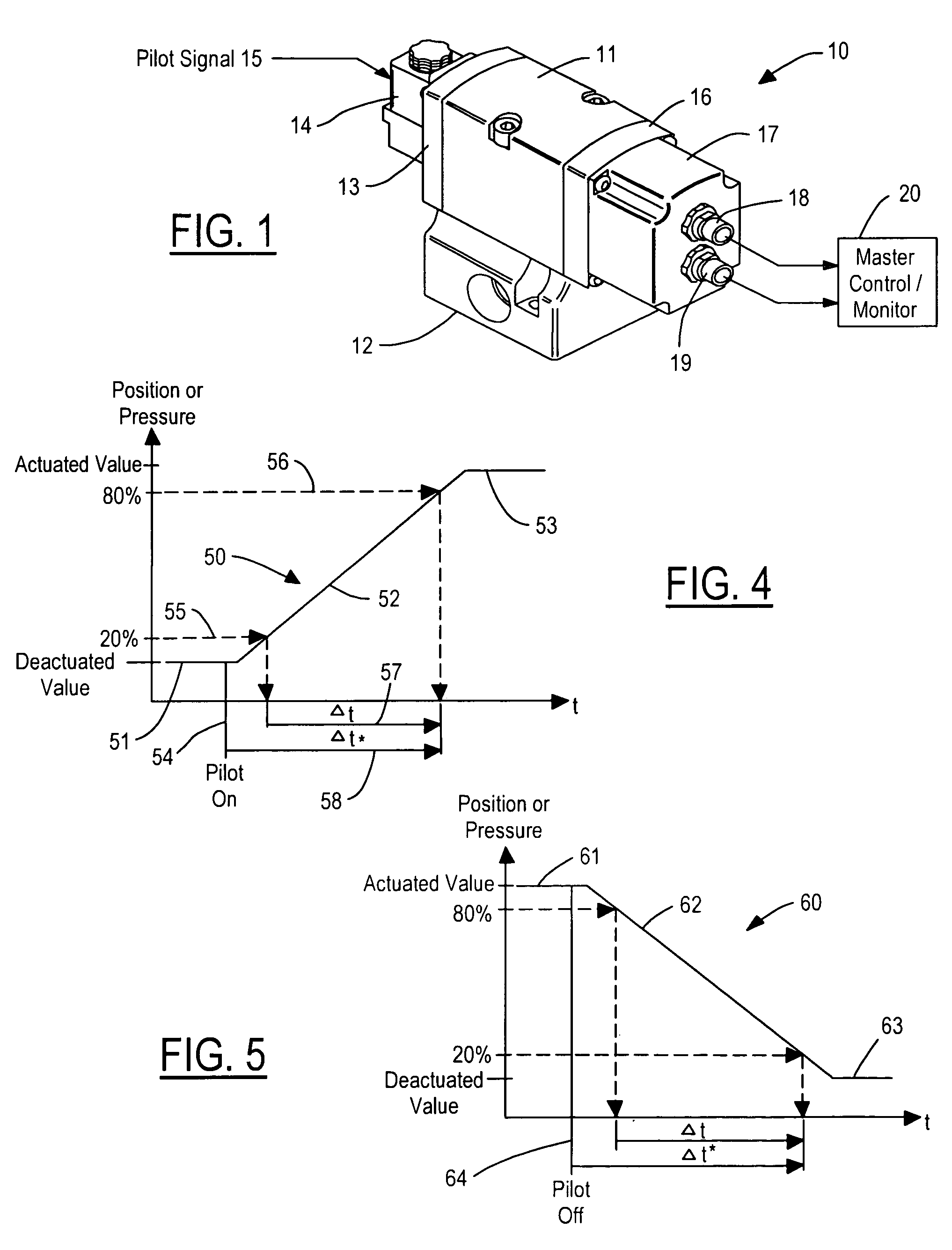
[0019]Referring now to FIG. 1, a valve system 10 includes a valve body 11 mounted to a base 12. Valve body 11 includes conventional valve internal parts for supplying fluid between various ports in base 12. A cover plate 13 mounts a pilot valve 14 to valve body 11. A pilot command signal 15 coupled to pilot valve 14 may be an electrical signal when the pilot valve 14 is an electrical solenoid-operated valve or may be a pneumatic signal when pilot valve 14 is pneumatically controlled. An end cap 16 is provided for mounting a housing 17 to valve body 11. Housing 17 includes the monitoring electronics of the present invention in the form of a logic unit and has end connectors 18 and 19 for electrically connecting the electronics to a master control / monitor 20.
[0020]Valve body 11, base 12, and pilot valve 14 may be any type of conventional fluid control valves employing one or more moving valve elements. Single valves, double valves, two-position valves, three-position valves, or any ot...
PUM
 Abstract
Description
Claims
Application Information
 - R&D
- Intellectual Property
- Life Sciences
- Materials
- Tech Scout
- Unparalleled Data Quality
- Higher Quality Content
- 60% Fewer Hallucinations
Browse by: Latest US Patents, China's latest patents, Technical Efficacy Thesaurus, Application Domain, Technology Topic, Popular Technical Reports.
© 2025 PatSnap. All rights reserved.Legal|Privacy policy|Modern Slavery Act Transparency Statement|Sitemap|About US| Contact US: help@patsnap.com


