Conveyor system

a conveyor system and conveying system technology, applied in the direction of screening, solid separation, sieving, etc., can solve the problems of easy folding, difficulty in adjusting the load,

Active Publication Date: 2009-12-17
TEREX GB
View PDF9 Cites 11 Cited by
  • Summary
  • Abstract
  • Description
  • Claims
  • Application Information

AI Technical Summary

Benefits of technology

[0007]There may be provided at least one support means movably connected at a first end thereof to the base frame section and at a second end thereof to the mid frame section. In some embodiments there may be provided at least two such support means. Such support means can help to support the load of the conveyor on the base frame section.
[0009]It is also a desired feature of screening units that they should have longer conveyors. Since the conveyor systems generally extend upwardly and outwardly from the screening unit the longer the conveyor system is the further it extends away from the screening unit and to a greater height. This enables more material to be sorted and stock piled by the screening unit thus increasing the amount of material that can be sorted by the screening unit. An advantage of the conveyor system and screening unit according to the invention is that a longer conveyor belt may be incorporated in the screening unit, thus increasing height of the pile of material that can be sorted and thus the total amount of material that can be sorted by the screening unit before it becomes necessary to move the unit to a new position.
[0011]A further advantage is that the side conveyor frame may be folded in the transport position within the width of the screening unit and therefore does not add to the width or envelope of the body of the screening unit. In a preferred embodiment the conveyor system may be rotated to extend rearwardly of a screening unit in the inoperative position. This is particularly advantageous in that it is preferable to add to the length of the screening unit rather than to the width of the unit since long loads are easier to transport in terms of regulations than wide loads.
[0015]In a preferred embodiment the telescopic legs may increase and decrease in length as the mid frame rotates about the first pivot axis and moves the mid frame section from the operative to the inoperative position. The first support member may increase in length while the second support member decrease in length. The support members may vary in length by differing amounts. As the mid frame rotates about the first pivot axis the support members change in length and the members pivot about the further pivot joints. As the support members move about the further pivot joints the opposing plates and the pin mounted therebetween rotate as the rotatable shaft rotates. The upper pivot joint allows further movement between the mid frame and the support means such that the support means allow the mid frame to rotate about the first pivot axis.
[0018]The support members act to support the mid frame section when in its operative position, thereby increasing the overall strength of the frame.
[0026]As the mid and upper frame sections preferably pivot in one plane only, the pivot joints by which the mid and upper frame sections are connected may be simple. For example, it is not necessary to provide universal type pivot joints. The second pivot axis about which the upper frame section pivots with respect to the mid frame section, and the first pivot axis about which the mid frame section pivots with respect to the base frame section are arranged to be obliquely angled with respect to each other. This allows the mid and upper frame sections to rotate to lie within or against an envelope of a screening unit to which the frame may be attached.

Problems solved by technology

This has become increasingly important as transportation of wide loads on roads and motorways has become more restrictive.
Foldable conveyor systems and foldable frames for such systems have been developed, but many of these have experienced problems, for example in the ease of folding, or the strength of the frame and particularly in relation to the overall width or envelope of the folded screening unit.
A disadvantage that has arisen with such arrangements is that relative lengths of sections of the frame may be restricted by the need to fold the frame over and along a body of the screening unit.

Method used


Image

  • Conveyor system
  • Conveyor system
  • Conveyor system

Examples


Embodiment Construction

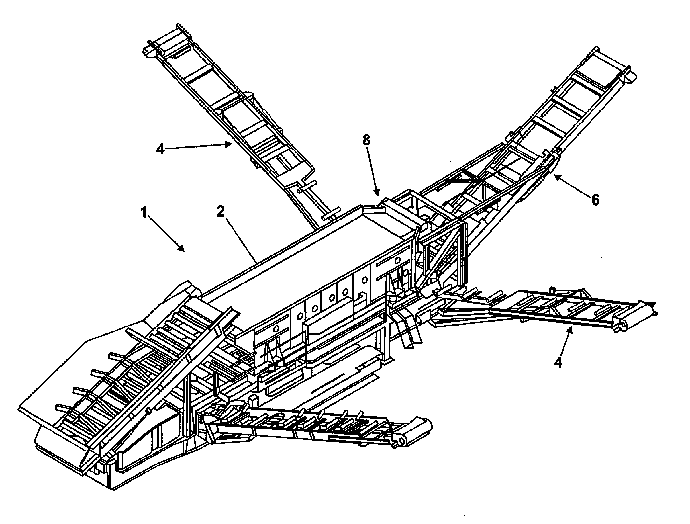
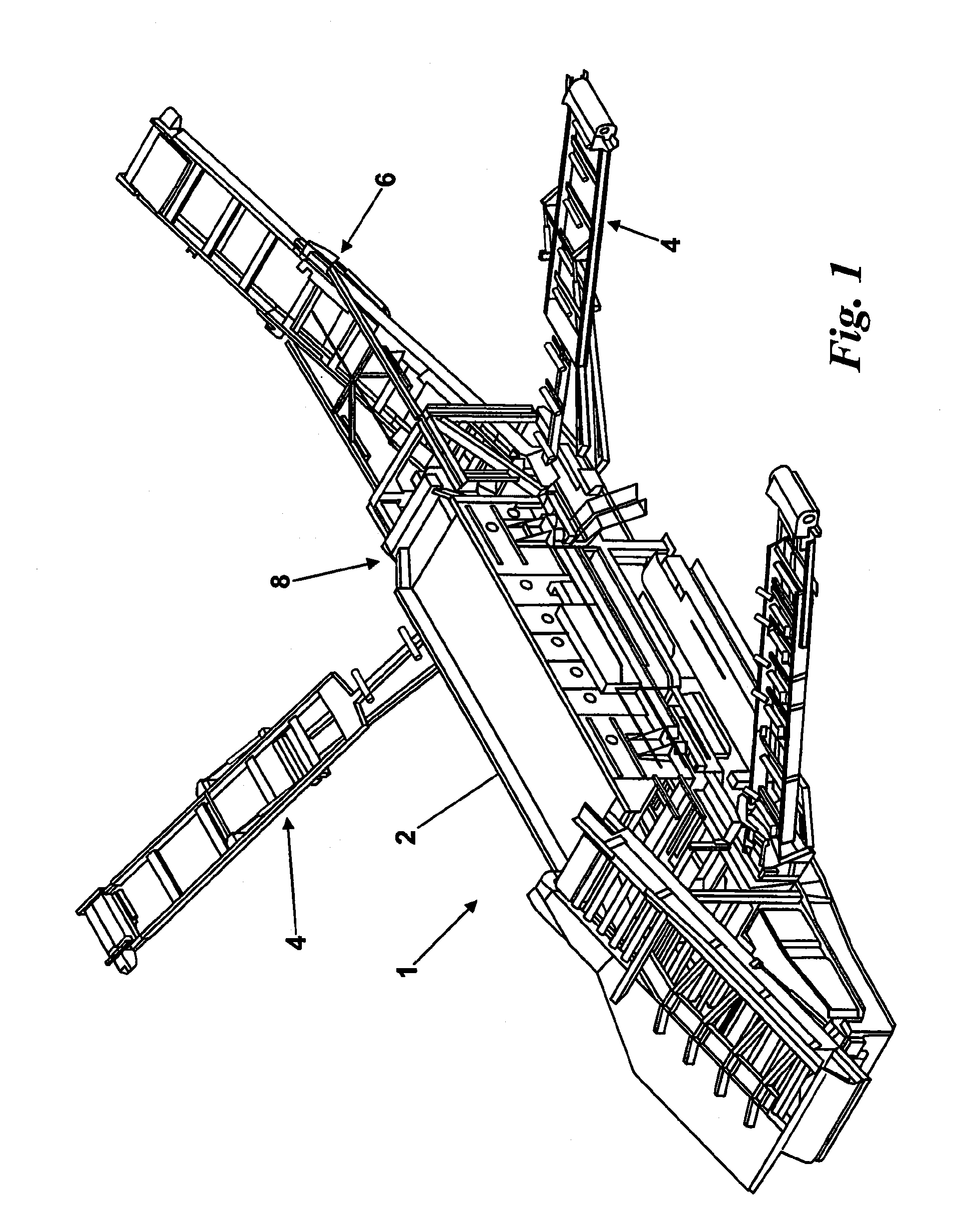
[0043]A screening unit 1 comprises a body 2 which has a number of side conveyor systems generally indicated at 4. The screening unit also has at least a rear conveyor system 6 extending from a rear 8 of the screening unit 1.

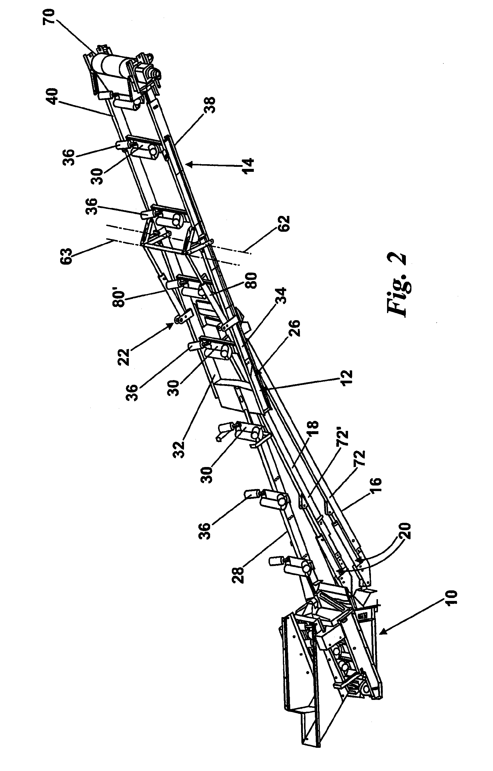
[0044]A typical conveyor system in accordance with the invention may be seen in FIG. 2. Each side conveyor system comprises a base frame section 10, a mid frame section 12 connected to the base frame section, and an upper frame section 14 connected to the mid frame section. A first support member 16 and a second support member 18 are each connected between the base frame section and the mid frame section. A first operating means 20 is connected between the base frame section and the mid frame section, and a second operating means 22 is connected between the mid frame section 12 and the upper frame section 14. In the illustrated embodiment the first and second operating means 20 and 22 each comprise a pair of hydraulic rams the operation of which will be described...


PUM


Abstract

A foldable side frame for a side conveyor system of a screening unit for processing materials that includes means of placing the side conveyor system within an envelope of a screening device. The system comprises providing a base, mid and upper frame section of the side conveyor system with a first operating means acting to pivot the mid frame relative to the base frame about a first pivot axis and a second operating means acting to pivot the upper frame relative to the mid frame about a second pivot axis in which in the operative position the first and second axes are obliquely angled relative to one another.

Description

CROSS-REFERENCE TO RELATED APPLICATION[0001]This application claims priority to Great Britain Patent Application GB 0808463.4 filed on May 9, 2008 and the contents of which are expressly incorporated herein.BACKGROUND[0002]The invention relates to a conveyor system, and particularly to foldable frames for side conveyor systems of screening units.[0003]Screening units are used in many applications for the processing of various materials, such as sand, gravel, stone, soil and aggregate material. Such units comprise a screening device, and one or more conveyor systems on frames to carry the various types or grades of screened material to individual stockpiles. It is desirable that these screening units be movable from place to place within a worksite, and, indeed, from site to site. To achieve this one or more of the conveyor systems, particularly any side conveyor systems, are usually placed in a folded position prior to transport of the unit. If the unit is to be moved to a different...

Claims


Application Information

Patent Timeline
Patent Type & Authority Applications(United States)
IPC IPC(8): B65G21/14
CPCB65G21/14B07B1/005B65G41/002E02F7/02
Inventor DEVLIN, ANTHONYMCDERMOTT, PAUL
Owner TEREX GB
Why Eureka
Try Eureka