Container, in particular a bottle, made of a thermoplastic material, provided with a reinforced base

a thermoplastic material and container technology, applied in the direction of rigid containers, clamping mechanisms, closures, etc., can solve the problems of inability to reliably withstand additional stress, weakly rounded bases traditionally provided for containers intended for still liquids, and containers with shapes which were satisfactory a few years ago are no longer suitabl

Inactive Publication Date: 2009-12-17
SIDEL PARTICIPATIONS SAS
View PDF15 Cites 50 Cited by
  • Summary
  • Abstract
  • Description
  • Claims
  • Application Information

AI Technical Summary

Benefits of technology

[0026]This structure allows great freedom of practical realization. Thus, the dome can be rounded. The arch can also be rounded, for example in a spherical zone, or also be shaped as the frustrum of a cone.
[0027]In practice, it can advantageously be provided that said annular zone forming a foundation has a diameter which is comprised between approximately 70% and 90% of the diameter of the body, and that said arch has a height which is comprised between approximately 10% and 25% of the diameter of the annular zone forming a foundation.
[0028]It can also be beneficial that the base has a height which is approximately 15% greater than the diameter of the annular zone forming a foundation.

Problems solved by technology

However, they do not offer sufficient resistance to withstand an additional stress, even though small, that may be due for example to an internal excess pressure.
The weakly rounded bases traditionally provided for containers intended for still liquids cannot reliably withstand, without deformation, even a pressure as small as that generated by the inertization process.
For this reason, bases of containers having shapes which were satisfactory a few years ago are no longer suitable, because of the perceptible reduction in the quantity of material used.
Thus experience showed that a reinforced base designed as described above was no longer satisfactory, in a lightened version thereof, even for excess pressures of only approximately 1×10⁵ Pa.
The aforementioned bases, in their lightened version, cannot thus reliably withstand such an excess pressure without yielding.
However, this also relates to a container intended to be manufactured with a substantial quantity of thermoplastic material and which does not make it possible to obtain the lightened version that manufacturers require today.
Containers provided with such bases therefore prove to be more costly and their correct shaping during moulding is more tricky.
It is therefore not desirable to provide bases of this type to containers subjected to an inertization step, even less so as they are shaped to withstand much higher pressures than those created by the inertization operation: their high resistance and the extra cost which is associated with them appear excessive for the envisaged application.

Method used


Image

  • Container, in particular a bottle, made of a thermoplastic material, provided with a reinforced base
  • Container, in particular a bottle, made of a thermoplastic material, provided with a reinforced base
  • Container, in particular a bottle, made of a thermoplastic material, provided with a reinforced base

Examples


Embodiment Construction

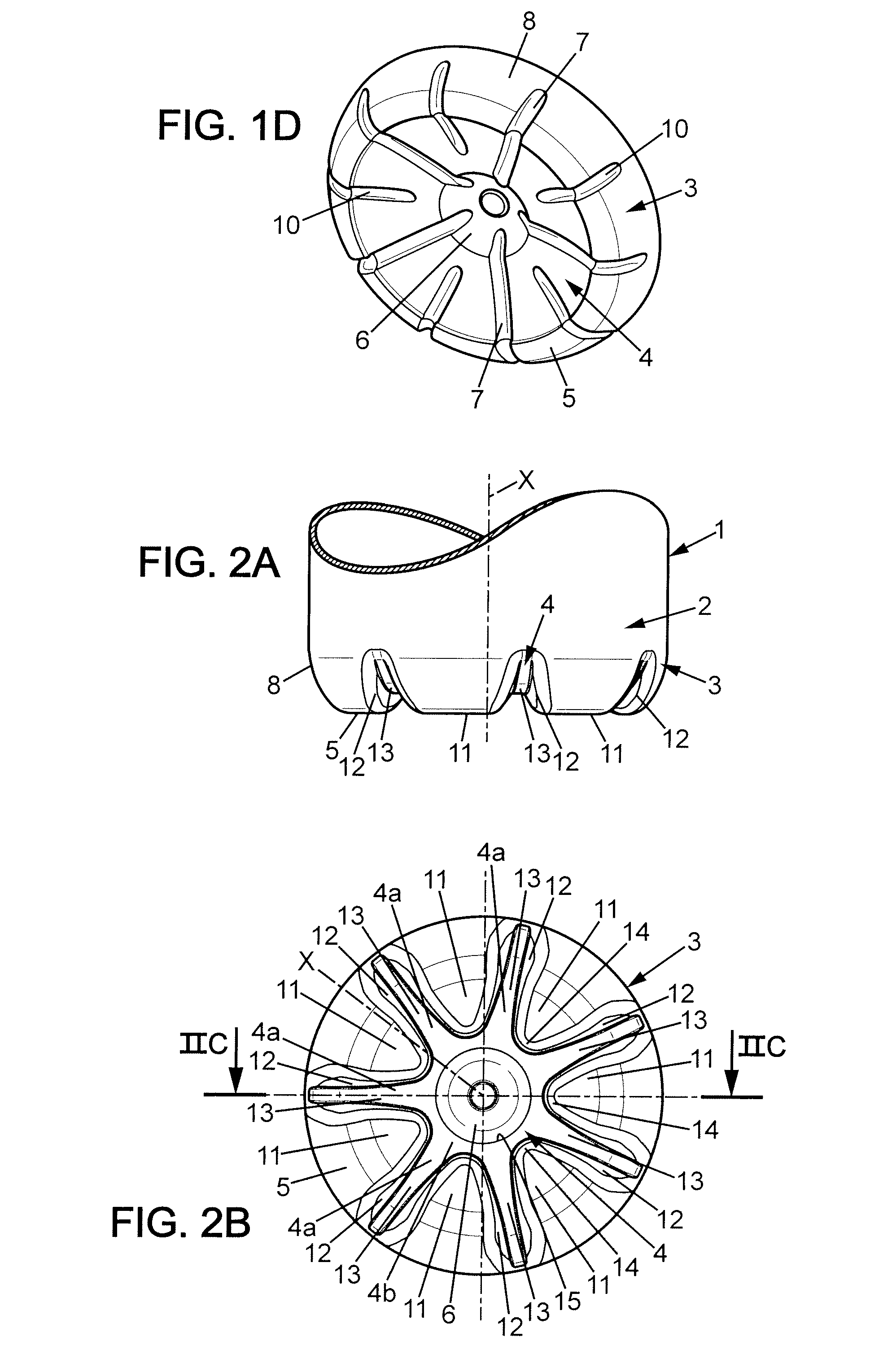
[0036]In the following description, the same reference numbers as were used previously in reference to FIGS. 1A to 1D will be kept to identify identical elements or parts.

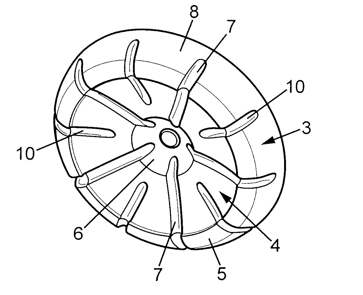
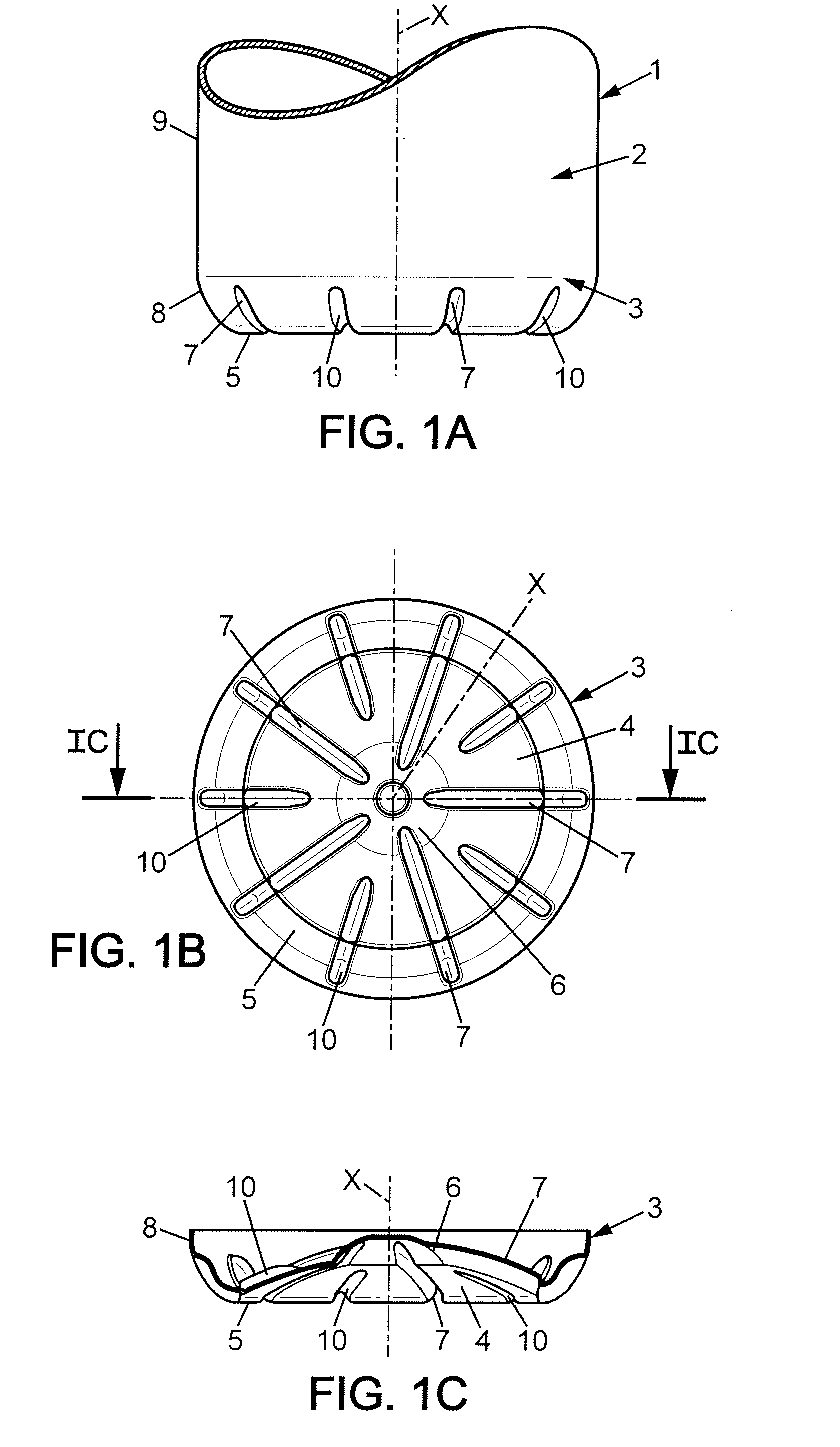
[0037]Referring first of all to FIGS. 2A to 2D, the container 1, here a bottle having the general shape of a substantially cylindrical body of revolution, made of a thermoplastic material such as PET, has a base 3 which comprises:[0038]a concave arch 4 having a concavity turned towards the outside of the container,[0039]a dome 6 projecting towards the inside of the container and having a concavity turned outwards, opening at the centre of said arch 4,[0040]an annular zone 5 surrounding the base of said arch 4, close to but set back from the periphery of the base 3,[0041]and forming a substantially flat foundation due to which said base 3 can stably rest on a flat support, and[0042]ribs in the form of grooves opening outwards, extending substantially radially across said annular zone 5 forming a foundation and risin...


PUM


Abstract

Thermoplastic container (1) having a body (2) and a base (3) comprising: a concave arch (4), a concave dome (6) opening at the centre of said arch (4), an annular zone (5) surrounding the base of said arch and forming a flat foundation, claw-shaped zones (11) radially extending the base of the body (2) and offset projecting outwards relative to the arch, and radial grooves (12) delimited between the zones (11) in the shape of claws, said grooves having bottoms (13) which are formed by radial sections (4a) of the arch and which have a radially variable depth which is maximum in correspondence with said annular zone forming a foundation. Such a base is adapted for withstanding, without marked deformation, the hydrostatic pressure due to the liquid column increased by an excess pressure not exceeding approximately 2×10⁵ Pa.

Description

FIELD OF THE INVENTION[0001]The present invention relates to improvements made to containers, in particular bottles, made of a thermoplastic material such as PET, having a body extending between, at the top, a neck and, at the bottom, a base adapted for withstanding without marked deformation the hydrostatic pressure due to the liquid column increased by an excess pressure not exceeding approximately 2×10⁵ Pa, said base comprising:[0002]a concave arch having a concavity turned towards the outside of the container,[0003]a dome projecting towards the inside of the container and having a concavity turned outwards, opening at the centre of said arch,[0004]an annular zone surrounding the lower part of said arch and forming a substantially flat foundation by which said base can stably rest on a flat support, and[0005]ribs shaped as grooves opening outwards, extending substantially radially across said annular zone forming a foundation and rising into the wall connecting with the wall of t...

Claims


Application Information

Patent Timeline
Patent Type & Authority Applications(United States)
IPC IPC(8): B65D8/00
CPCB65D1/0284
Inventor BOUKOBZA, MICHEL
Owner SIDEL PARTICIPATIONS SAS
Why Eureka
Try Eureka