Controllable high luminance illumination with moving light-sources

a technology of moving light sources and controllable illumination, which is applied in the direction of fixed installations, lighting and heating apparatuses, instruments, etc., can solve the problems of complex and costly thermal management arrangements, cannot meet the requirements of high luminance, and the leds have not yet been widely adopted, so as to facilitate the control of the illumination configuration/pattern, the effect of high luminan

Active Publication Date: 2015-01-22
LUMILEDS
View PDF10 Cites 6 Cited by
  • Summary
  • Abstract
  • Description
  • Claims
  • Application Information

AI Technical Summary

Benefits of technology

[0005]In view of the above-mentioned and other drawbacks of the prior art, a general object of the present invention is to provide an improved illumination device, in particular providing for a high luminance as well as facilitating control of the illumination configuration / pattern provided by the illumination device.

Problems solved by technology

For some applications, where the maximum luminance is a key feature, LEDs, however, have not yet been widely adopted.
Due to thermal management issues and the so-called droop, the loss of efficiency at excessive drive current densities, currently available LEDs still cannot meet the requirements on high luminance over time for, for example, automotive headlamp applications without rather complex and costly thermal management arrangements, such as large cooling fins and / or fans.
Hereby, various illumination configurations can be achieved, but with a complex arrangement having many moving parts that have to be individually controlled.
Furthermore, heat management issues still remain to be addressed.

Method used


Image

  • Controllable high luminance illumination with moving light-sources
  • Controllable high luminance illumination with moving light-sources
  • Controllable high luminance illumination with moving light-sources

Examples


Embodiment Construction

[0033]In the following description, the present invention is mainly described with reference to an automotive headlamp application with a light-source unit that is arranged to be rotated about a rotational axis.

[0034]It should, however, be noted that this by no means limits the scope of the invention, which is equally applicable to other applications, such as floodlight applications, as well as to other configurations. An example of a further configuration is that the light-source unit may be arranged to be moved along a linear path past the optical element.

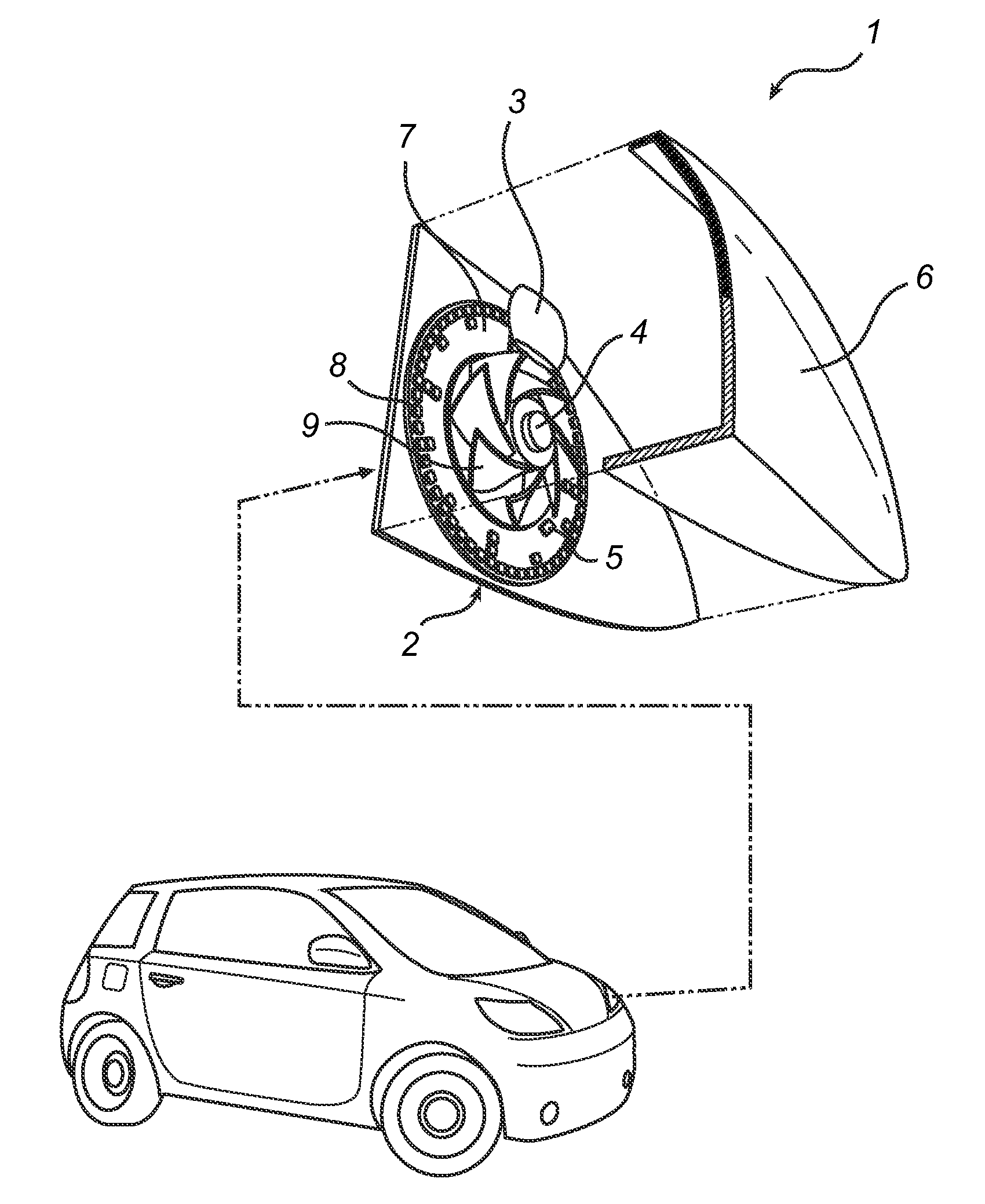
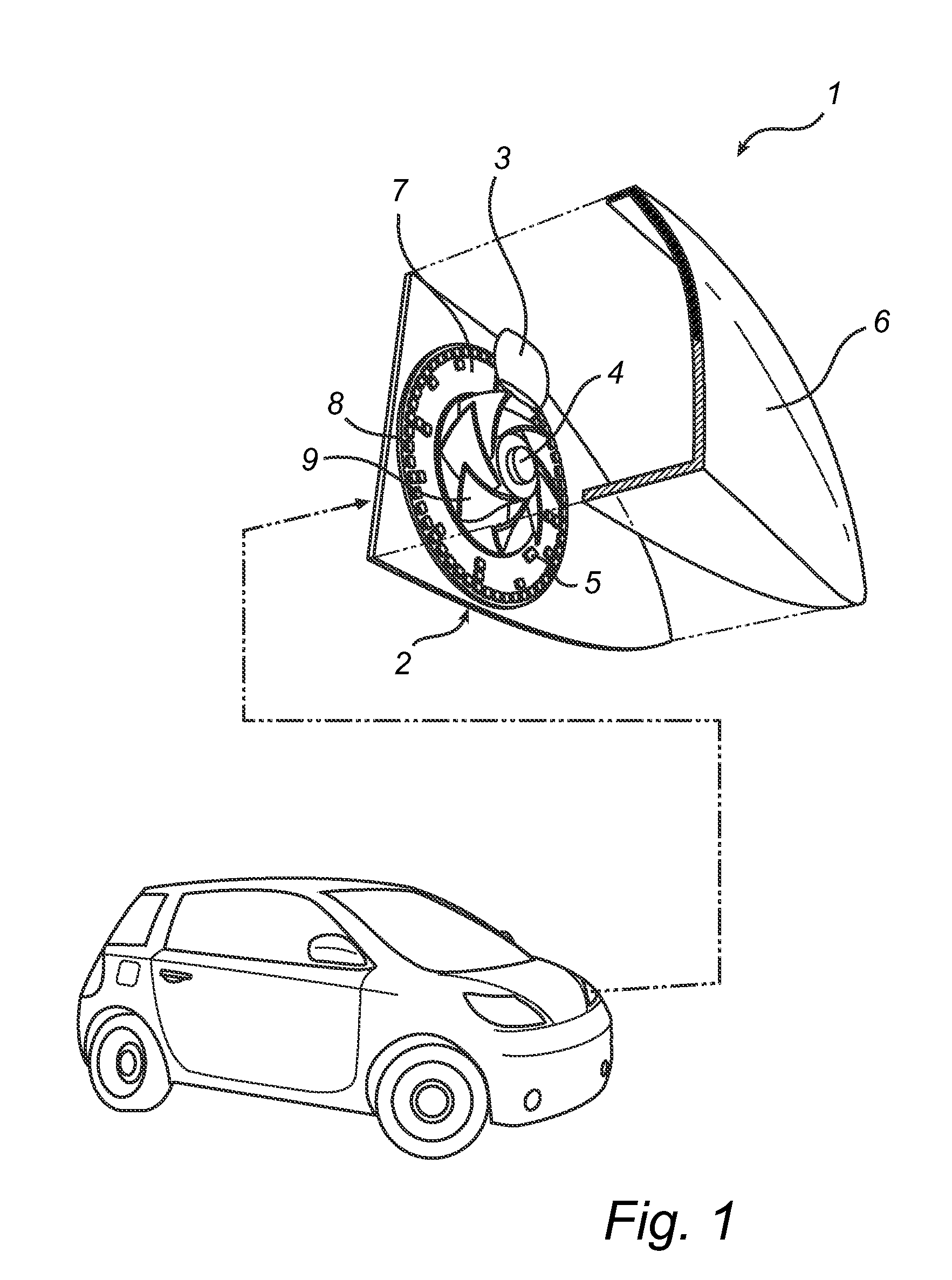
[0035]FIG. 1 schematically illustrates an exemplary application for embodiments of the illumination device according to the present invention, in the form of an automotive headlamp 1 comprising a light-source unit 2, projection optics, here shown as a simple lens 3, an actuator in the form of an electric motor 4, a control unit 5 for controlling operation of the automotive headlamp 1, and a transparent protective cover 6. As is s...


PUM


Abstract

The present invention relates to an illumination device (1) for providing a controllable illumination configuration. The illumination device comprises a light-source unit (2; 20) comprising a plurality of individually controllable solid state light-sources (8); and an optical element (3) arranged to modulate light from the solid state light-sources through a modulation area (16) of the optical element (3). The illumination device (1) further comprises an actuator (4) connected to the light-source unit (2) and controllable to move the light-source unit relative to the optical element (3) in such a way that the solid state light-sources (8) pass the modulation area (16) of the optical element (3) in succession; and a control unit (5) configured to control each of the solid state light-sources (8) to emit light with a time-varying intensity corresponding to the illumination configuration while the solid state light-source (8) moves past the modulation area of the optical element.

Description

FIELD OF THE INVENTION[0001]The present invention relates to a device and method for providing a controllable illumination configuration.BACKGROUND OF THE INVENTION[0002]As the performance of solid state light-sources, such as light-emitting diodes (LEDs) is rapidly improving, while prices are dropping, new applications for solid state light-sources are emerging. For some applications, where the maximum luminance is a key feature, LEDs, however, have not yet been widely adopted. Due to thermal management issues and the so-called droop, the loss of efficiency at excessive drive current densities, currently available LEDs still cannot meet the requirements on high luminance over time for, for example, automotive headlamp applications without rather complex and costly thermal management arrangements, such as large cooling fins and / or fans. The same is valid for other applications, such as for spotlights etc.[0003]In addition, for automotive headlamps as well as for spotlights etc, it w...

Claims


Application Information

Patent Timeline
Patent Type & Authority Applications(United States)
IPC IPC(8): B60Q1/16F21S8/10B60Q1/14
CPCB60Q1/1415F21S48/325F21Y2105/00B60Q1/16F21Y2101/02F21S48/115F21S48/1742F21S48/1747F21S48/34B60Q2900/30F21S41/143F21S41/147F21S41/151F21S41/657F21S41/663F21S45/43F21S45/60B60Q1/04B60Q1/10B60Q1/12
Inventor DROSS, OLIVER
Owner LUMILEDS
Why Eureka
Try Eureka