Intrusion detection system for underground/above ground applications using radio frequency identification transponders

a radio frequency identification and intrusion detection technology, applied in the direction of burglar alarm short radiation actuation, burglar alarm electric actuation, instruments, etc., can solve the problems of inability to detect vandalism or terrorist threats to the exterior of the facility and the immediate vicinity of a structure or area to be protected, cctv camera effectiveness is less, ir sensors and cctv camera damage, etc., to achieve the effect of reducing site work in engineering, reducing the cost of establishing

Inactive Publication Date: 2009-12-17
CECIL KENNETH B
View PDF19 Cites 11 Cited by
  • Summary
  • Abstract
  • Description
  • Claims
  • Application Information

AI Technical Summary

Benefits of technology

[0007]The teachings of the present invention results in many benefits. For example, the manner in which the intrusion detection system of the present invention is constructed around or under a security zone would greatly reduce the site work in engineering that was formerly required in the prior art devices. Since off-the-shelf RFID transponders are utilized, the cost of establishing the intrusion detection system with respect to the security zone is greatly reduced. Furthermore, because the RFID transponders are passive, maintenance and repair work are simplified or significantly eliminated. This is particularly true since the RFID transponders operate on energy received from the electromagnetic field radiated from operating transceivers. Each of the transponders has a unique encrypted identification code further adding to the security of the system by eliminating non-encrypted transponders from being powered by the EM field.
[0008]Because the present invention does not require that the transponders or transceivers are affixed to metal fences, the system can be easily installed on hard surfaces, such as brick or concrete walls as well as the side of buildings and metal structures.
[0009]The present invention is also designed to identify the exact longitudinal locations of an intrusion in real time within 18 inches (46 cm). It would also result in a very low false alarm rate since blowing debris and small animals will not cause an intrusion alarm.

Problems solved by technology

Although a large amount of time, effort and money has been budgeted to agencies like the Department of Homeland Security, these intrusions and attempts to protect individuals as well as property have not lessened the threat.
Access control devices supervise access at perimeter doors of a facility, but fail to detect vandalism or terrorist threats to the exterior of the facility and the immediate vicinity of a structure or area to be protected.
Limitations are the rule since CCTV cameras are less effective at night and both IR sensors and CCTV cameras are compromised by fog and rain.
Furthermore, IR and microwave sensors do not locate the point of the attempted intrusion and fence cables are limited to the use with metal fences.
Buried cable sensors require significant site engineering.
None of the present solutions can locate intrusions accurately on hard surfaces such as brick walls or buildings.
Vibration based systems often result in false-positive alarms due to trucks traveling on nearby roads, weather, lightening, sonic booms from military aircraft, vibrations from trees / shrubs and animals as well as earthquakes, tremors, seismic rumblings and explosions.
Repair and maintenance are frequent and costly.
Therefore, an intrusion is sensed by interference in the ability of the transponders to receive the EM field by an individual entering the field.

Method used


Image

  • Intrusion detection system for underground/above ground applications using radio frequency identification transponders
  • Intrusion detection system for underground/above ground applications using radio frequency identification transponders
  • Intrusion detection system for underground/above ground applications using radio frequency identification transponders

Examples


first embodiment

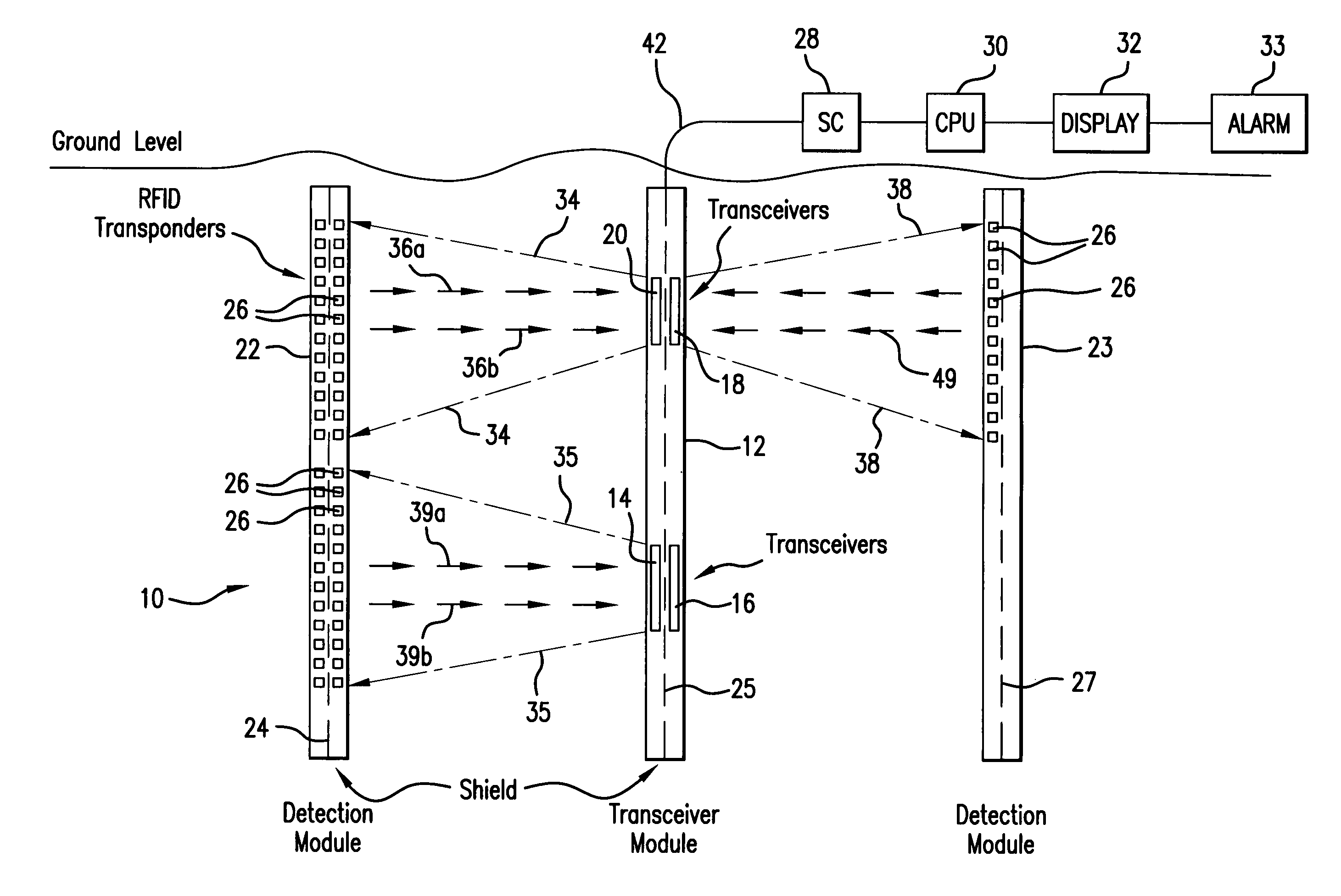
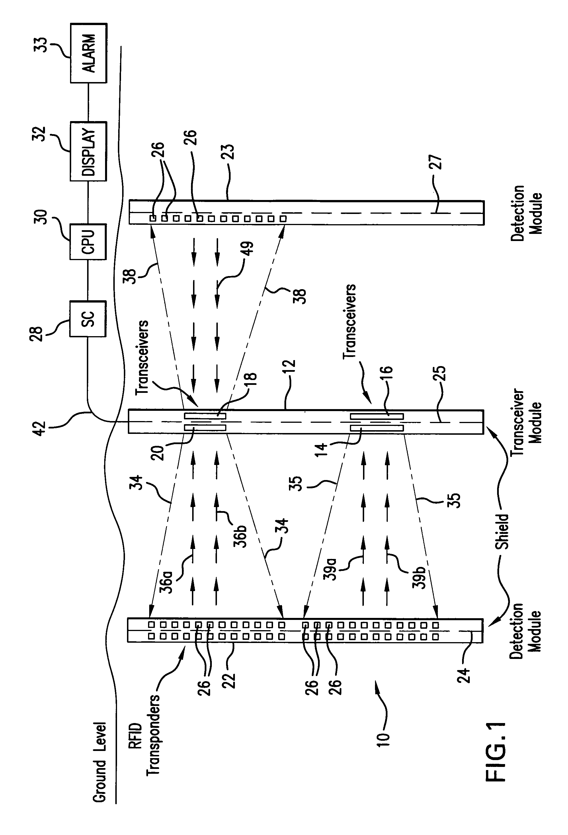
[0015]As illustrated in FIG. 1, the present invention would include a transceiver module (TM) 12 as well as two detection modules (DM) 22, 23. As can be appreciated, additional TMs as well as additional DMs could be employed. The TMs and the DMs would be buried in holes drilled vertically along the perimeter of the below ground level and parallel to each security zone (SZ) 10. The TM 12 would generally consist of a PVC or plastic pipe placed vertically in the ground. The TM would include radio frequency (RF) transceivers 14, 16, 18 and 20. It can be appreciated that more or less transceivers can be included in each TM. The detection modules 22, 23 would consist of a plurality of radio frequency identification (RFID) passive transponders placed in the PVC or plastic pipe at approximately one foot intervals. Similar to the TM 12, the PVC or plastic pipe is vertically inserted into the ground. The detection modules 22, 23 would be separated from the TM 12 at a distance of approximately...

second embodiment

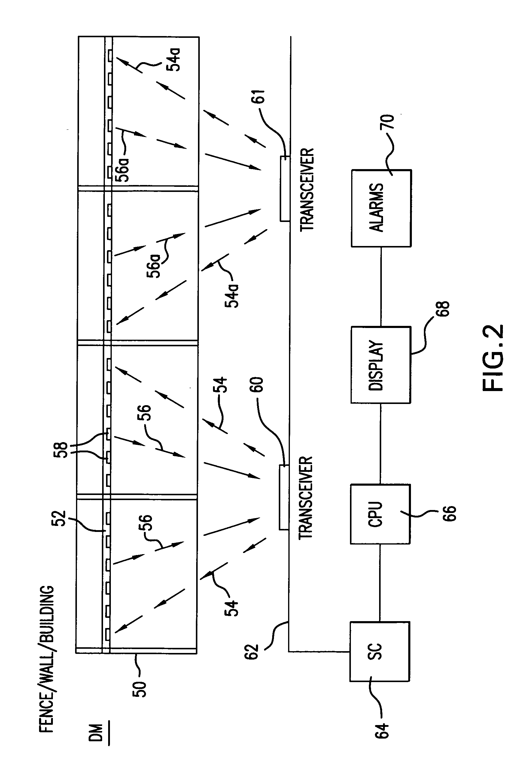
[0027]FIG. 2 illustrates the present invention. This embodiment would allow the present invention to be used for the above ground supervision of a fence, brick or concrete walls, monuments and other objects 50. Above ground transceivers 60 or 61 would broadcast coded RF signal 54, or 54a respectively, to power a plurality of RFID transponders 58 arranged on or in a cable 52 which could be housed in a PVC pipe provided horizontally on and attached to the fence, building or other structure 50. Alternatively, the RFID transponders 58 could be arranged on a surface or embedded in or behind surfaces (i.e., wood, brick / concrete). The RFID transponders 58 would respond to one of the transceivers 60, 61 through electromagnetic inductive coupling and transmit their unique code 56 to be received by its respective transceiver 60, 61. The transceiver 60, 61 would periodically or continually broadcast the electromagnetic field as its unique code for each transceivers 60, 61 and the RFID transpon...


PUM


Abstract

The present invention is directed to an underground as well as above ground system and method of determining the intrusion into a security zone. One or more transceivers would transmit a unique electromagnetic signal which would power a response from one or more RFID transponders. Each of the transponders would transmit a unique code to the transceiver indicating that there has been no intrusion in the vicinity of that transponder. Failure of a transponder to receive a signal produced by a transponder, would indicate the existence of an intrusion. The transponders as well as the transceivers can be provided in a PVC pipe buried in the ground, or provided in or on a structure located on or above the ground.

Description

FIELD OF THE INVENTION[0001]The present invention is directed to the field of establishing an underground or above ground intrusion detection system utilizing radio frequency identification (RFID) transponders.BACKGROUND OF THE INVENTION[0002]Over the last several years and particularly since September 11, there has been a significant increase in the number of intrusions into various security zones as well as acts of international terrorism. Although a large amount of time, effort and money has been budgeted to agencies like the Department of Homeland Security, these intrusions and attempts to protect individuals as well as property have not lessened the threat.[0003]Access control devices supervise access at perimeter doors of a facility, but fail to detect vandalism or terrorist threats to the exterior of the facility and the immediate vicinity of a structure or area to be protected.[0004]Existing perimeter security systems and the prior art consist of CCTV cameras, sense cables e...

Claims


Application Information

Patent Timeline
Patent Type & Authority Applications(United States)
IPC IPC(8): G08B13/24
CPCG08B13/24
Inventor CECIL, KENNETH B.
Owner CECIL KENNETH B
Why Eureka
Try Eureka