Two-channel plastic optical fiber (POF) rotary joint

a plastic optical fiber and rotary joint technology, applied in the field of two-channel plastic optical fiber rotary joints, can solve the problems of difficult to accurately measure the magnetic interaction, the plastic fiber application of almost all prior arts of fiber optical rotary joints is hardly used, and the system of facing lenses is very difficult to be manufactured, etc., to achieve the effect of compact structure and low profil

Active Publication Date: 2009-12-17
PRINCETEL
View PDF10 Cites 20 Cited by
  • Summary
  • Abstract
  • Description
  • Claims
  • Application Information

AI Technical Summary

Benefits of technology

[0012]The first object of the present invention is to utilize the plastic optic fibers, to realize a two channel fiber optic rotary joints which can simultaneously transmit optic signals through a single mechanical rotational interface with a very low-profile and compact structure.
[0013]

Problems solved by technology

But the facing lens systems are very difficult to be fabricated.
But it could be very difficult for the magnetic interaction to accurately ensure the synchronous ro

Method used


Image

  • Two-channel plastic optical fiber (POF) rotary joint
  • Two-channel plastic optical fiber (POF) rotary joint
  • Two-channel plastic optical fiber (POF) rotary joint

Examples


Embodiment Construction

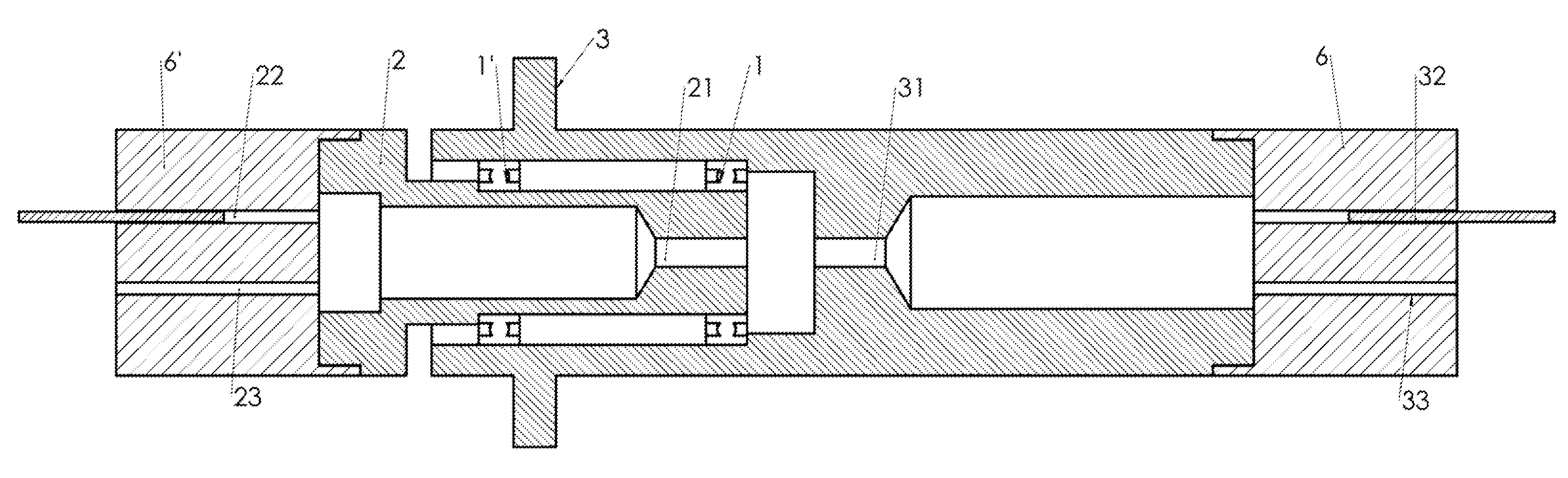
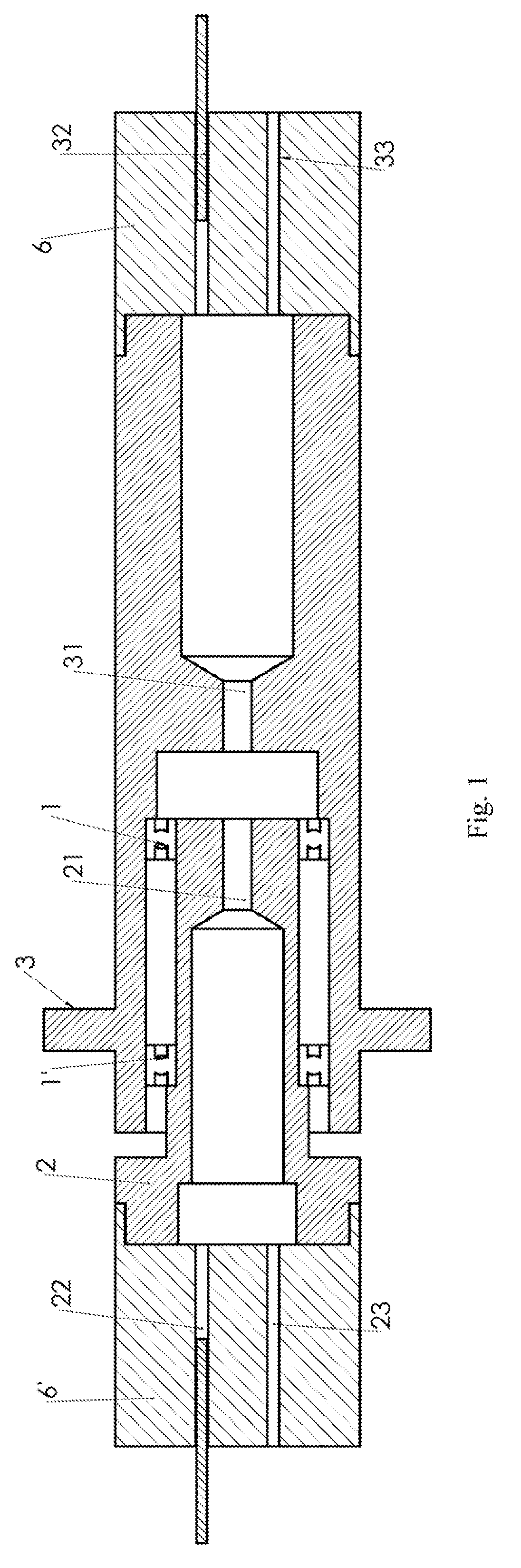
[0019]Refers to FIG. 1, a preferred mechanical embodiment of the present invention consists of a rotatable component 2 with a central hole 21, a fixed component 3 with a central hole 31, a pair of bearing 1 and 1′ to enable the component 2 and 3 rotatable relatively. The rotatable component 2 further comprises fiber holder 6′ which has two coupling holes 22 and 23. The fixed component 3 further comprises fiber holder 6 which has two coupling holes 32 and 33. The axis of the rotation is the geometrical axis of the component 2 and 3.

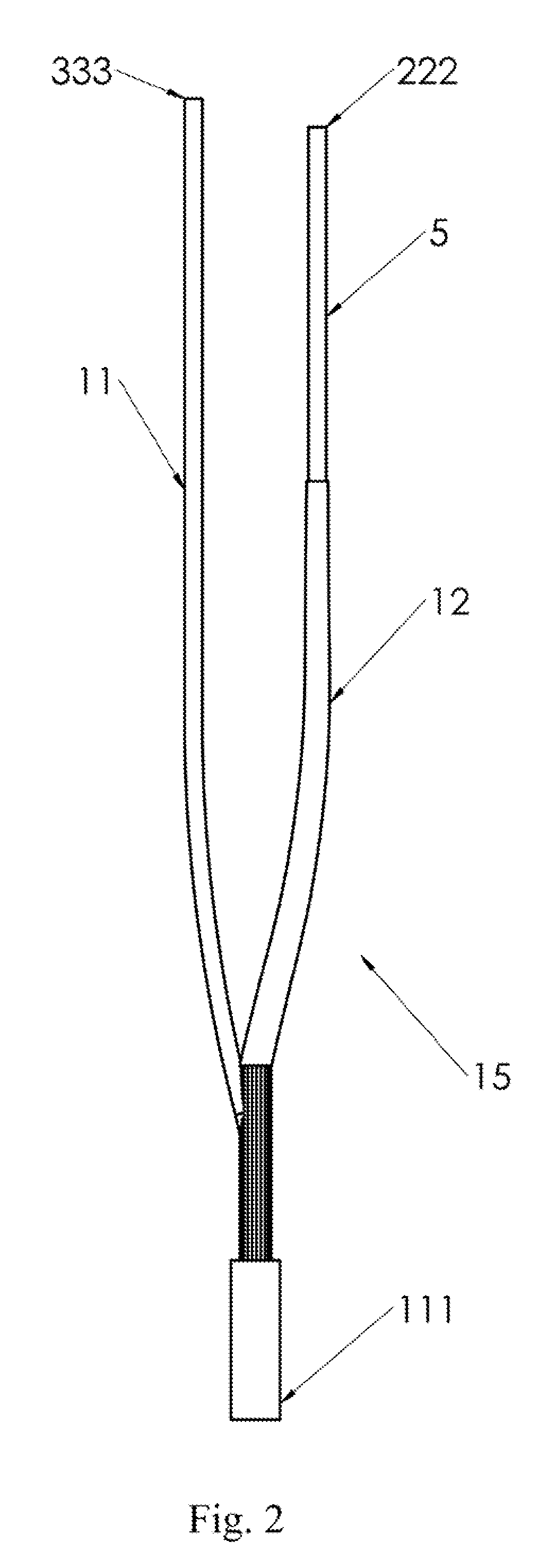
[0020]As shown in FIG. 2, a typical “Y” shaped plastic optical fiber bundle assembly 15 (or 15′) has its bottom side 111 (or 111′), the first top side 333 (or 333′) and second top side 222 (or 222′). The “Y” shaped plastic optical fiber bundle assembly 15 (or 15′) includes a large-core plastic fiber 11 (or 11′), a group of small-core plastic fibers 12 (or 12′) and a coupling fiber 5 (or 5′). Said large-core plastic fiber 11 (or 11′) has its front portion a...


PUM


Abstract

The present invention connects two independent plastic optical fiber channels simultaneously, in which optic signals can be transmitted along two optic passes through a single mechanical rotational interface. The first channel of light path consists of a pair of plastic optic fibers with larger-core, co-axially fixed in 2 holders respectively. The light signal from one of the fiber can be directly coupled into another fiber. A number of smaller-core plastic optic fibers for second channel of light path are circumferentially arranged in the peripheral space of the first channel fibers. They are blind-spot free during rotation and are ideal for machine control applications such as SERCOS Interfaces. The rugged design permits underwater usage. Damaged fibers can be easily replaced without costly repairs of the device itself.

Description

[0001]This application claims priority of US Provisional Patent Application number: 61073082, filed date: Jun. 17, 2008BACKGROUND OF THE INVENTION[0002]1. Field of the Invention[0003]The present invention relates generally to the field of apparatus for fiber optical communication, and more particularly, to a two-channel plastic optical fiber (POF) rotary joint.[0004]2. Description of Related Art[0005]typical fiber optical rotary joint consists of a fixed fiber holder and a rotatable fiber holder which are relatively rotatable each other to allow uninterrupted transmission of optical signals through the rotational interface from fibers on any one of the holders to the fibers on another holder.[0006]There are three types of optical fiber commonly used: single mode glass fiber, multimode glass fiber and plastic optical fiber (POF). Glass fibers which support many propagation paths or transverse modes are called multimode fibers. Fibers which support only a single mode are called single...

Claims


Application Information

Patent Timeline
IPC IPC(8): G02B6/42G02B6/04
CPCG02B6/3604G02B6/02033
Inventor ZHANG, BOYING B.ZHANG, HONG
Owner PRINCETEL
Why Eureka
Try Eureka