Facet joint implants and delivery tools

a facet joint and implant technology, applied in the field of facet joint implants and delivery tools, can solve the problems of radicular pain, high surgery cost, pain and disability of a large segment of the population, and achieve the effect of preventing relative movement along the plan

Active Publication Date: 2009-12-17
PROVIDENCE MEDICAL TECH
View PDF100 Cites 293 Cited by
  • Summary
  • Abstract
  • Description
  • Claims
  • Application Information

AI Technical Summary

Benefits of technology

[0033]In another embodiment, a spinal distraction implant may include a pair of stacked structures separated by a sloping plane and a fastener positioned at an angle through the pair of structures thereby preventing relative movement along the plane.

Problems solved by technology

Chronic back problems cause pain and disability for a large segment of the population.
Spinal stenosis results in a reduction of foraminal area (i.e. the available space for the passage of nerves and blood vessels), which may compress cervical nerve roots and cause radicular pain.
These surgeries may be expensive and beget additional surgeries due to changing the biomechanics of the neck.
Moreover, these surgeries may be highly invasive leading to long recovery times.

Method used


Image

  • Facet joint implants and delivery tools
  • Facet joint implants and delivery tools
  • Facet joint implants and delivery tools

Examples


first embodiment

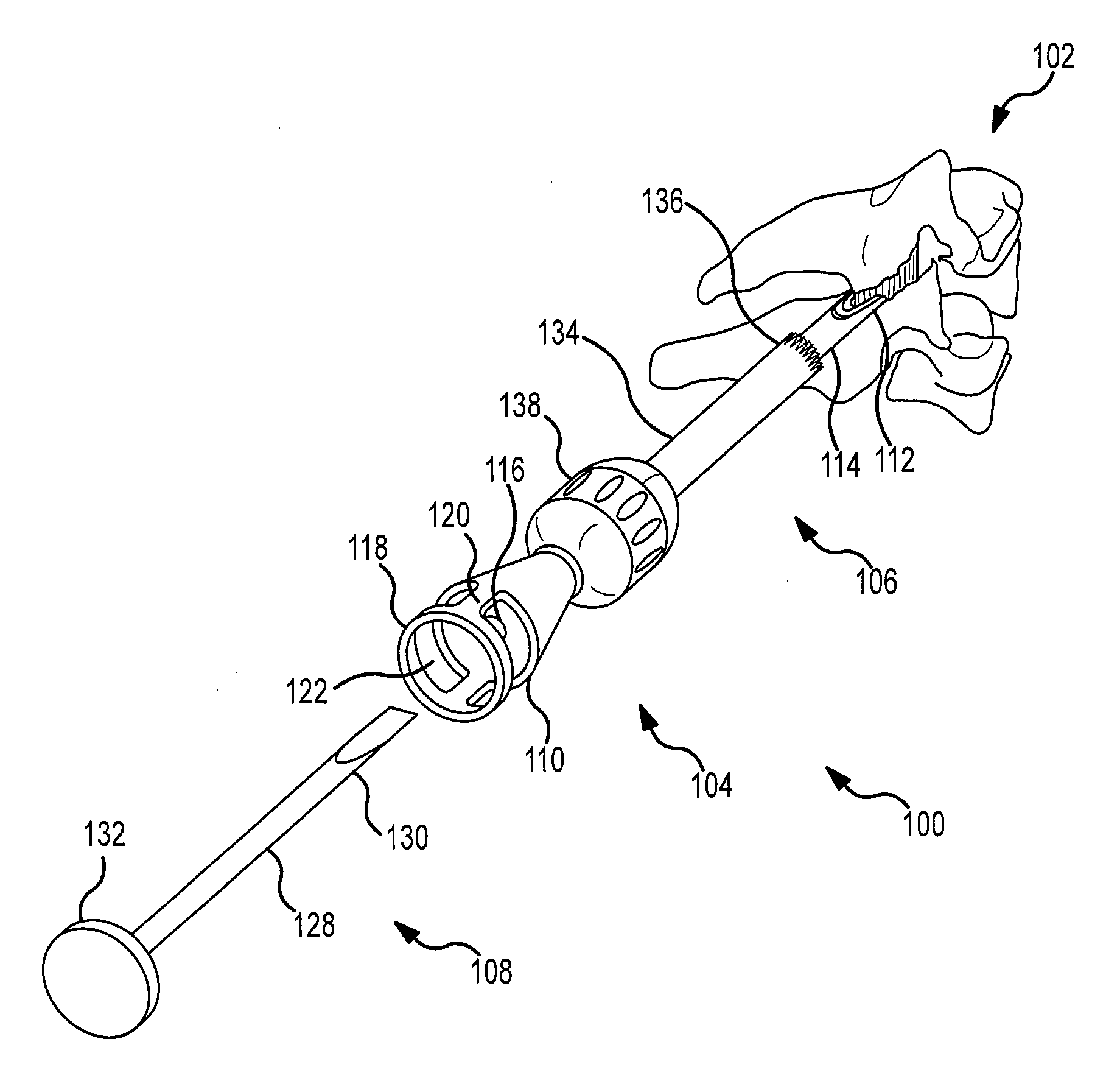
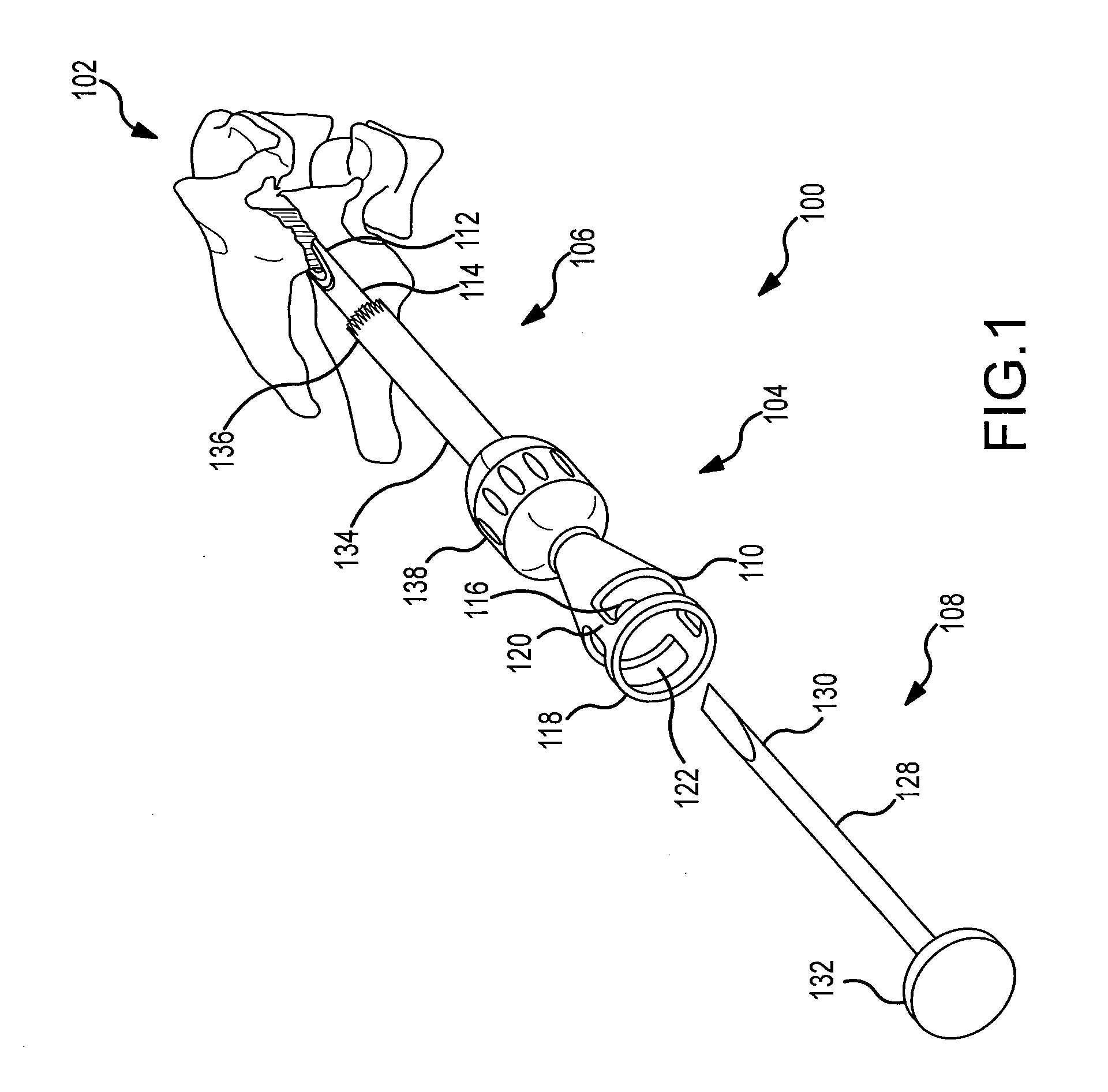
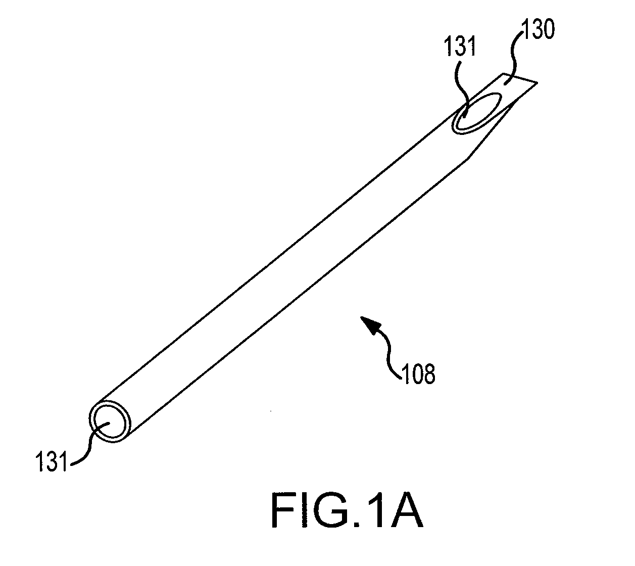
[0191]Referring now to FIGS. 1-28, a tool and an implant is shown. FIG. 1 shows the tool 100 in position posterior to the spine 102. The tool 100 includes a delivery device 104, a decorticator 106, and a chisel 108.

[0192]The delivery device 104 may include a receiving assembly 110 at a proximal end, anchoring forks 112 at a distal end, and a generally tubular shaft 114 defining a longitudinal axis and extending between the receiving assembly 110 and the anchoring forks 112. The tubular shaft 114 may have an annular shaped cross-section with an inner radius and an outer radius, where the difference between the two radii defines a thickness of the tubular shaft 114.

[0193]The receiving assembly 110 of the delivery device 104 may have a generally conical outer surface defining a generally hollow volume or solid mass. The conical outer surface may have a longitudinal axis that coincides with that of the tubular shaft 114. The conical outer surface may be defined by a first radius at a pr...

second embodiment

[0255]In the second embodiment, as shown, a directional facet screw 436 may be advanced through the inferior facet surface until it engages with a facet spacer / plate 440 that is inserted in between the facet surfaces within the facet capsule. As the screw 436 makes contact with the facet spacer / plate 440, the flat surface of the spacer / plate 440 may push up against the opposing superior facet surface causes distraction and forward translation. This separation of the facet surfaces results in increased foraminal area and reduced nerve root compression.

third embodiment

[0256]In a third embodiment, the spacer / plate 440 may have a shape to allow the screw 436 to pass through a first end and the other end to be placed in the facet joint. In this embodiment, the C-shaped spacer 440 may be positioned in the joint, thereby slightly distracting the joint. The screw may then penetrate a first end of the spacer 440 thereby anchoring the spacer 440 in the joint. The screw may then be advanced through the inferior facet surface until it engages with the spacer / plate 440. As the screw 436 makes contact with the facet spacer / plate 440, the flat surface of the spacer / plate 440 may push up against the opposing superior facet surface causes distraction and forward translation. In some embodiments, the screw may penetrate the spacer and aid in fixing the joint.

[0257]FIGS. 61A-C show yet another embodiment of an implant 442. In this embodiment, bracket type structures 444 may be attached to the superior and inferior lateral masses. The bracket type structures 444 m...


PUM


Abstract

A spinal joint distraction system is disclosed and may include a delivery device, a driver assembly, and an internal actuator, where the driver assembly is adapted to be hold an implant and be sleevably inserted into the delivery device and the internal actuator is adapted to advance an implant distractor to distract the implant, the system also including an implant, a chisel, an injector, a gripping tool, and a dilator set. Several embodiments of an implant are disclosed as well a method of placing an implant.

Description

CROSS-REFERENCE TO RELATED APPLICATIONS[0001]The present application claims priority to: U.S. Provisional Application No. 61 / 059,723, which was filed on Jun. 6, 2008 and is entitled Spine Distraction Device; U.S. Provisional Application No. 61 / 109,776, which was filed on Oct. 30, 2008 and is entitled Facet Joint Implants; and U.S. Provisional Application No. 61 / 169,601, which was filed on Apr. 15, 2009 and is entitled Facet Joint Implants and Delivery Tools. The present application also claims priority to, and is a continuation-in-part (“CIP”) application of, U.S. patent application Ser. No. 12 / 317,682, which was filed on Dec. 23, 2008, is entitled Facet Joint Implants and Delivery Tools, and claims priority to Provisional Applications 61 / 059,723 and 61 / 109,776. The contents of all of the above-mentioned patent applications are all hereby incorporated by reference herein in their entireties.FIELD OF THE INVENTION[0002]The following detailed description relates to a device for distra...

Claims


Application Information

Patent Timeline
Patent Type & Authority Applications(United States)
IPC IPC(8): A61B17/00A61B17/60A61B17/58A61F11/00H04L45/02H04L45/24H04L45/28
CPCA61B17/025A61F2/4611A61B17/1604A61B17/1659A61B17/1671A61B17/1735A61B17/1757A61B17/7064A61B17/863A61B17/8811A61B17/8819A61B17/8822A61B2017/00424A61B2017/00429A61B2017/0256A61B2017/320028A61B2019/304A61B2019/307A61B17/0642A61B2090/037A61B2090/034H04L45/28A61B17/7074A61B2090/031A61F2/4405A61F2/4455A61F2/447A61F2002/30131A61F2002/30168A61F2002/30176A61F2002/30266A61F2002/30289A61F2002/30378A61F2002/30405A61F2002/30451A61F2002/30471A61F2002/30484A61F2002/30507A61F2002/3052A61F2002/30523A61F2002/30538A61F2002/30556A61F2002/30599A61F2002/30733A61F2002/30841A61F2002/3085A61F2002/30904A61F2002/448A61F2002/4627H04L45/00H04L45/02H04L45/22H04W28/04
Inventor MCCORMACK, BRUCE M.SMITH, JEFFREY D.
Owner PROVIDENCE MEDICAL TECH
Why Eureka
Try Eureka