Opposite radial rotary-piston engine of choronski-modification

a technology of choronski and piston engine, which is applied in the direction of reciprocating piston engine, positive displacement engine, combustion engine, etc., can solve the problems of limited operation resource for loaded parts, construction does not eliminate side forces, and complex units with substantial friction losses, etc., to achieve the effect of extending the engine life, enhancing the efficiency, size, weight and power variety of the engine, and reducing the lateral force momen

Active Publication Date: 2009-12-24
EVGENI CHORONSKI +1
View PDF12 Cites 1 Cited by
  • Summary
  • Abstract
  • Description
  • Claims
  • Application Information

AI Technical Summary

Benefits of technology

[0015]A two-stroke opposite radial rotary-piston engine is proposed in the present disclosure, comprising a block including sleeves, pairs of pistons disposed within the sleeves and oppositely movable, a power takeoff shaft, two parallel positioned rotors mounted thereon having an inner surface formed by a closed curved line. The rotors have concaved surface portions. The engine comprises cross-like traverses pair-wise spanning the pistons. The traverses are associated with engagement means, cooperating with the concaved portions. The engine comprises support bearings, coupled to the traverses. Support bearings include an exte

Problems solved by technology

It is a complicated unit with substantial friction losses, which has a limited operation resource for its loaded parts.
The construction does not eliminate the side forces exerted by the piston upon the cylinder walls.
The construction is complicated and difficult to balance (which is admitted by its author).
The place of contact with the housing experiences high friction and heating, and thus will have a short operation resource.
That engine however has also certain drawbacks and limitations.
Reaction forces produced in support bearings are very significant that leads to a short operation resource period.
This necessitates the use of complicated sealing means that, as a rule, have very limited operation resource (typically 100

Method used


Image

  • Opposite radial rotary-piston engine of choronski-modification
  • Opposite radial rotary-piston engine of choronski-modification
  • Opposite radial rotary-piston engine of choronski-modification

Examples


Embodiment Construction

[0034]While the invention may be susceptible to embodiment in different forms, there are shown in the drawings, and will be described in detail herein, specific embodiments of the present invention, with the understanding that the present disclosure is to be considered an exemplification of the principles of the invention, and is not intended to limit the invention to that as illustrated and described herein.

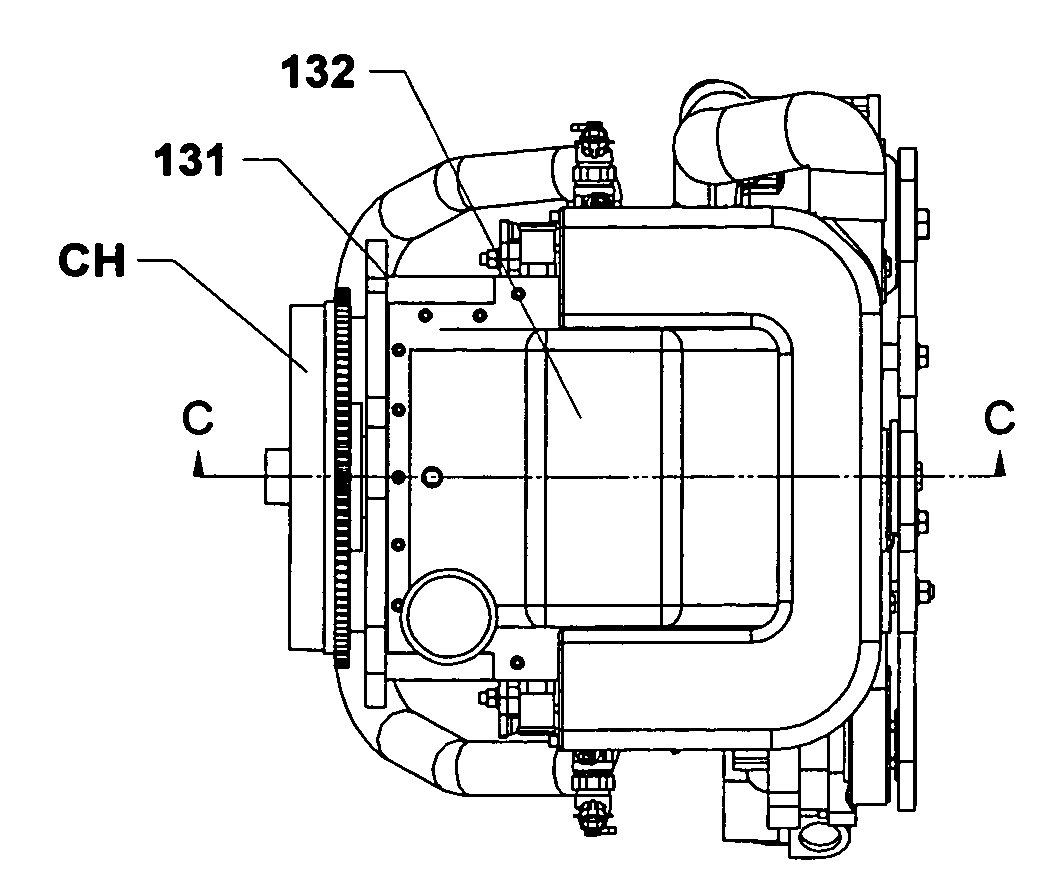
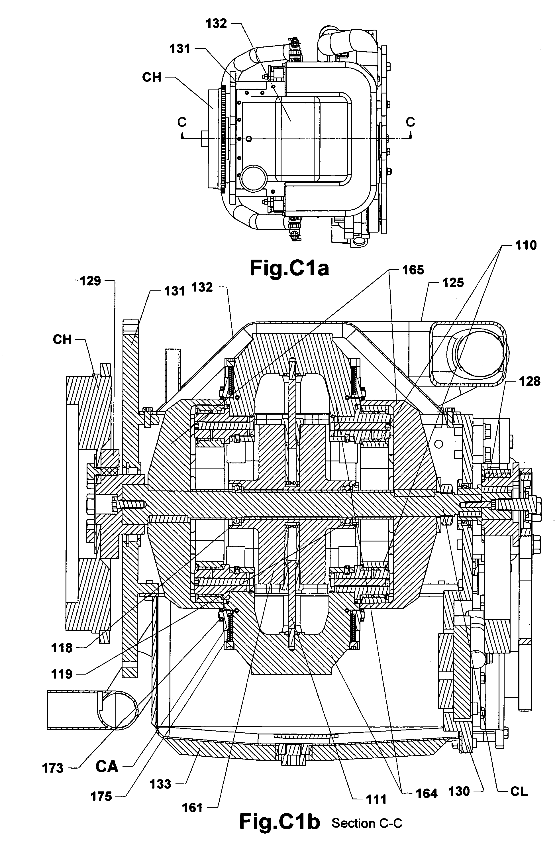
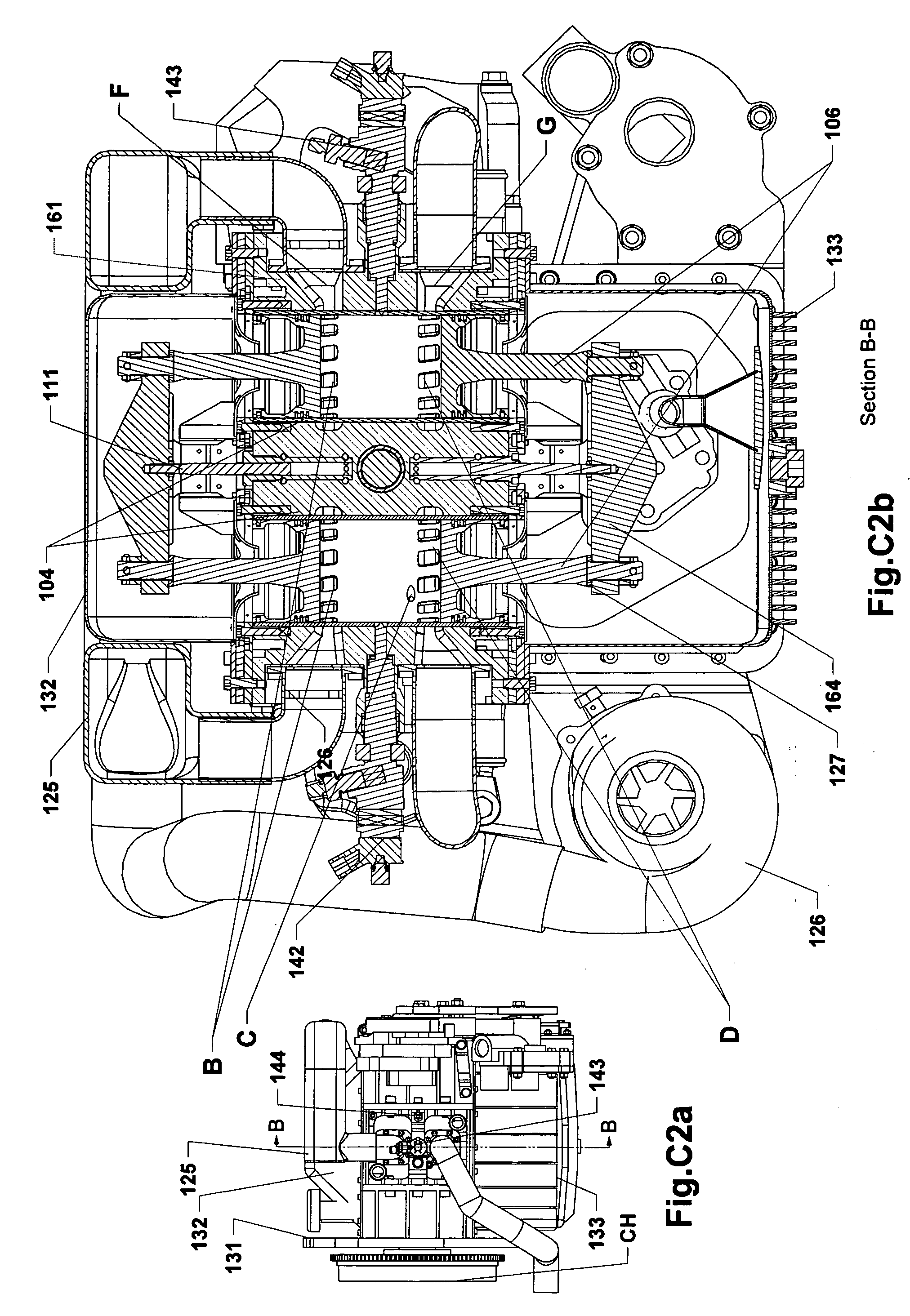
[0035]A preferred embodiment of the inventive engine is a two-stroke internal combustion engine featuring oppositely disposed pistons movable toward each other, which movement is converted into the spinning of rotors, also featuring the straight blowing of air through cylinders with the straight injection of fuel, and with liquid cooling. The inventive two-stroke engine can be embodied as a number of modules (herein called module ‘NM’ distinctly from the module ‘EM’ introduced in the parent application), and these modules can be assembled into a more powerful module engine, a nu...


PUM


Abstract

A two-stroke opposite radial rotary-piston engine is proposed, comprising a block including sleeves, pairs of pistons disposed within the sleeves and oppositely movable, a power takeoff shaft, two parallel positioned rotors mounted thereon having an inner surface formed by a closed curved line. The rotors have concaved surface portions. Cross-like traverses are mounted, pair-wise spanning the pistons. The traverses are associated with engagement means, cooperating with the concaved portions. The engine comprises support bearings, coupled to the traverses. Support bearings include an external bushing, rolling over the rotor's inner surface, thereby impelling the rotor. The engagement means are mounted in the region of contact of the support bearings and rotors, thereby eliminating lateral force moment, extending the lifespan of the engine. Other elements, module engine embodiments with different angular positions of the rotors, and power installation embodiments are disclosed, enhancing the efficiency, size, weight, and power variety of the engine.

Description

CROSS REFERENCE TO RELATED APPLICATIONS[0001]This U.S. patent application is a continuation-in-part application of a U.S. patent application Ser. No. 12 / 214,488 filed on Jun. 19, 2008, hereby entirely incorporated by reference (herein further referred to as “parent application”).FIELD OF THE INVENTION[0002]The invention relates to opposite radial rotary-piston engines that can be utilized in ground vehicles, water vehicles, aircraft, in combinations with generators, etc.BACKGROUND OF THE INVENTION[0003]In the prior art there are known several constructions of centrifugal-piston or rotary-piston engines (herein further called ORPE), which are intended to eliminate certain disadvantages of conventional piston engines. E.g., such constructions are described in DE3907307, U.S. Pat. No. 6,279,518, U.S. Pat. No. 4,334,506, WO2005098202, RU2143572, and JP7113452. The latter, for instance, has the purpose “to suppress the side pressure applied to a piston, improve efficiency, reduce vibrati...

Claims


Application Information

Patent Timeline
IPC IPC(8): F02B53/00
CPCF01B7/04F02B75/282F01B9/06
Inventor EVGENI, CHORONSKIMOUKHAEV, BORIS
Owner EVGENI CHORONSKI
Why Eureka
Try Eureka